Method for producing golf club head and golf club head structure

A technology for golf club heads and manufacturing methods, which is applied in the field of golf club head manufacturing, and can solve problems such as welding bead flowing into the inside of the club head, affecting the service life of the club head, and failure to obtain ball hitting stability, etc., so as to improve Manufacturing efficiency, quality, metal combination, firm structure, and light weight

Inactive Publication Date: 2007-01-24
梁龙成
View PDF1 Cites 9 Cited by
  • Summary
  • Abstract
  • Description
  • Claims
  • Application Information

AI Technical Summary

Problems solved by technology

However, this combination method has gaps due to the combination of the club head panel setting hole and the ball striking panel, and hydrogen welding is generally used for welding; while the required temperature of hydrogen welding is relatively high, but the weld bead is relatively shallow and The heat source is scattered and the strength is weak. Compared with ionized gas PLASMA welding or laser welding, the temperature is lower, the weld bead is deep, the strength is good, and the heat source is concentrated. Compared with the advantages, the effect is not ideal. In addition, hydrogen welding Solder must be injected all the time, which is more likely to cause the solder to flow into the club head, resulting in uneven weight of the club head and displacement of the center of gravity, so that the club head cannot get the proper hitting stability when hitting the ball; however The manufacturing of existing

Method used


Image

  • Method for producing golf club head and golf club head structure
  • Method for producing golf club head and golf club head structure
  • Method for producing golf club head and golf club head structure

Examples


Embodiment 1

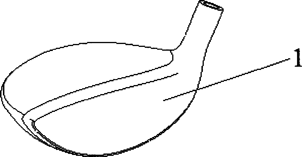
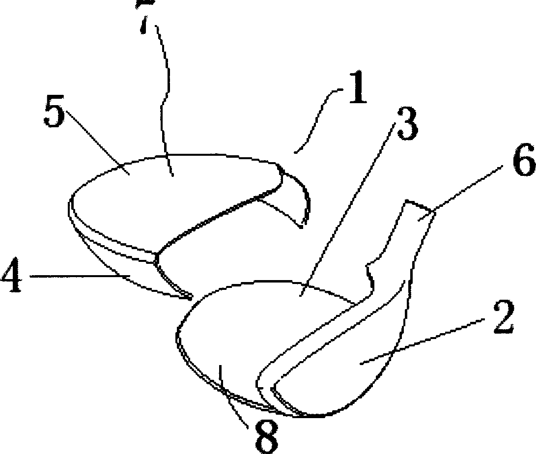
[0031] Embodiment 1: see figure 1 , figure 2 and Image 6 , a method for manufacturing a golf club head, comprising the steps of:

[0032] 1) A lower metal member 7 is formed by making the ball striking surface 2, the club head sole 3 and the club head tube 6 into one body. In this embodiment, the above-mentioned members are all made of stainless steel;

[0033] 2) Prefabricate a die-casting mold 11 that can be integrally die-casted with the club head side 4 and the ball cap 5. It can be divided into upper and lower halves 12, 13, and the hollow part 14 can be used to implant the aforementioned lower metal member 7;

[0034] 3) Fix the lower metal member 7 in the die-casting mold 11, and then put it into a high-temperature die-casting machine;

[0035] 4) pouring the metal liquid into the die-casting mold 11, and die-casting;

[0036] 5) After the metal is solidified, the die-casting mold 11 is separated to obtain the golf club head 1 .

[0037] The lower metal member 7...

Embodiment 2

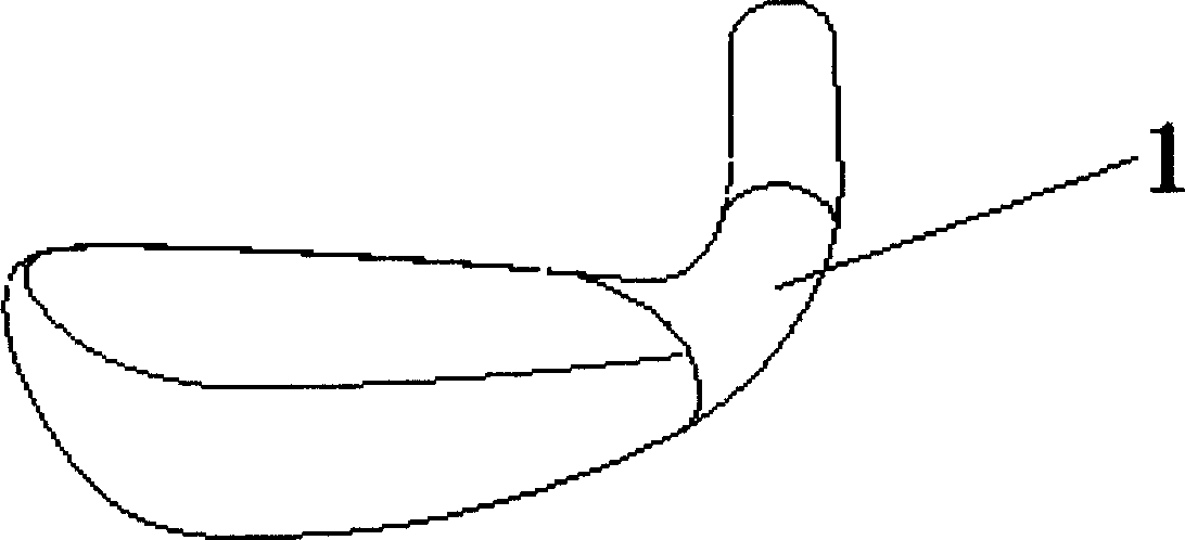
[0042] Example 2: see image 3 , Figure 4 , a method of manufacturing a golf club head, the basic steps of which are the same as those in Embodiment 1, the difference being that the step 2) also includes prefabricating a club head tube; the prefabricated mold can be The side part of the club head, the ball cover and the club head tube are jointly die-cast as one; the step 3) also includes the lower part of the club head tube and the club head bottom of the hitting surface. The metal component is fixed in the casting mold; the lower metal component is a multi-layer composite component made of elastic stainless steel.

[0043] An IRON-type golf club head structure manufactured by the aforementioned golf club head manufacturing method, its basic structure is the same as that of Embodiment 1, the difference is that the upper metal member 8 is connected with a An integrated club head tube 6; the overall outline of the club head 1 is flat, that is, an IRON type flat club head.

...


PUM


Abstract

The process of producing golf club head includes the following steps: 1. making the lower metal member of integrated driving plane and club bottom; 2. prefabricating one die-casting die for integrated club side and cover; 3. fixing the lower metal member inside the die-casting die; 4. pouring metal liquid for die casting; and 5. de-molding to obtain the golf club head. Thus made golf club head is one hollow structure including one lower metal member and one upper metal member combined through die casting.

Description

technical field [0001] The invention relates to a manufacturing method and structure of a golf club head, in particular to a manufacturing method and structure of a golf club head which is directly die-cast from two metal components with different properties, has a simple structure, and has high ball-hitting elasticity. Background technique [0002] Golf has gradually become a popular sports and leisure activity in the recent society, and due to the popularization of golf, golf equipment has gradually been paid attention to. Among the golf equipment, the most important golf club is the most important one. The quality of a club is related to the stability of the ball when hitting the ball and the flight state of the ball after hitting the ball. The worst result is the club head at the bottom of the club. [0003] The structure of the existing club head includes a hollow club head body and a panel. When manufacturing the club head, the manufacturer mostly uses the precision c...

Claims


Application Information

Patent Timeline
IPC IPC(8): B22D17/22B22D19/04
Inventor 梁龙成
Owner 梁龙成
Why Eureka
Try Eureka