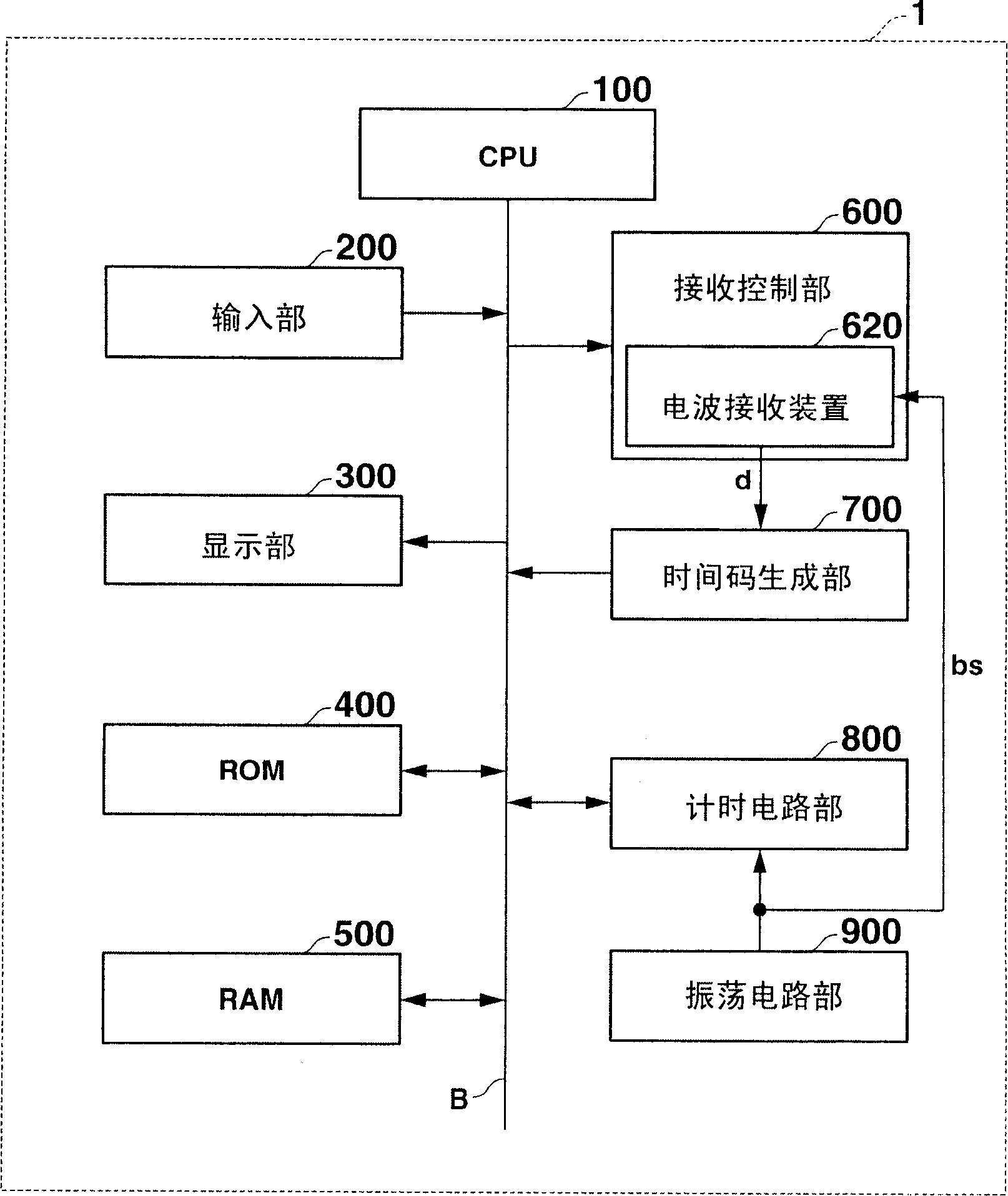
Radio wave receiving apparatus, radio wave receiving circuit and radio wave timepiece
A technology of radio wave reception and circuit, applied in the field of radio wave watch, can solve the problems of incomplete frequency, deviation, time required, etc.
- Summary
- Abstract
- Description
- Claims
- Application Information
AI Technical Summary
Problems solved by technology
Method used
Image
Examples
no. 1 example
[0125] First, the first embodiment will be described.
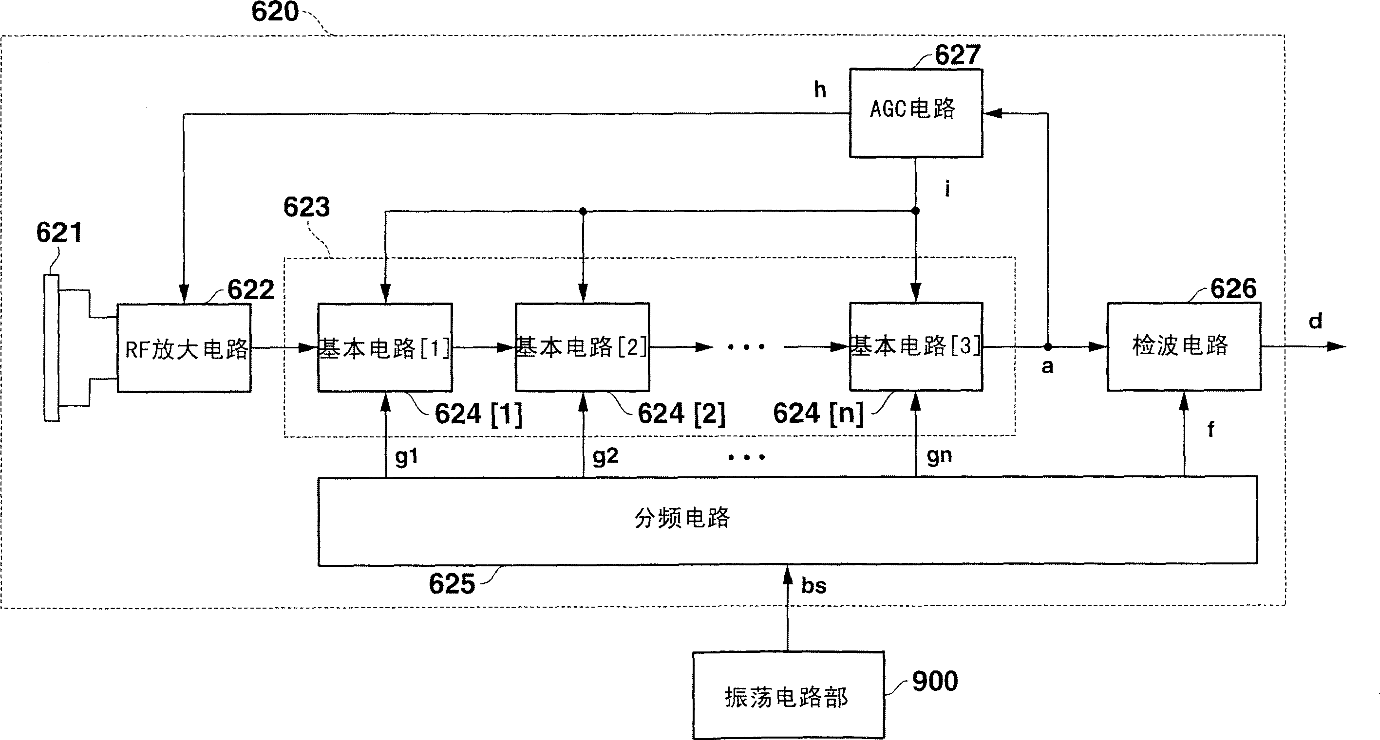
[0126] As described above, the multistage frequency conversion circuit 623 is constituted by connecting a plurality of basic circuits 624 in series, and these basic circuits 624 depend on the frequency of the received standard radio wave or which stage the basic circuit 624 is in the multistage frequency conversion circuit 623. , the pass bandwidth set in the filter circuit 6242 is different. Therefore, in the first embodiment, each basic circuit 624 is constituted as follows.
[0127] Figure 11A is a schematic diagram of the circuit configuration of the basic circuit 624A in the first embodiment. According to the figure, the basic circuit 624A has a mixer 6241 , a filter circuit 6242A, and an amplifier 6243 . The filter circuit 6242A has resistors R1 and R2 connected in series, a capacitor C, and a switch SW1 connected in parallel to the resistor R2. The switch SW1 is turned on / off (on / off) in accordance with, for e...
no. 2 example
[0133] The second embodiment will be described below.
[0134] The second embodiment is an embodiment in which the radio wave receiving device 620 can receive a plurality of standard radio waves of different frequencies so-called multi-band.
[0135] Figure 12 It is a block diagram showing the configuration of the radio wave receiving device 620B in the second embodiment. According to the figure, radio wave receiving device 620B has receiving antenna 621 , RF amplifier circuit 622 , multistage frequency conversion circuit 623B, frequency division circuit 625B, wave detection circuit 626 , and AGC circuit 627 .
[0136] Here, for becoming and being figure 2 The description of the same "function and structure" as described in "Function and structure" will be omitted.
[0137] The multistage frequency conversion circuit 623B is composed of a plurality of N stages of basic circuits 624 [ 1 ], 624 [ 2 ], . . . , 624 [N] connected in series. And in each of the basic circuits 6...
no. 3 example
[0149] Next, a third embodiment will be described.
[0150] The third embodiment is the same as the above-mentioned second embodiment, and is an embodiment of the multi-band radio wave receiving device 620. Figure 13A The basic circuit 624B is replaced by Figure 14A The point of the basic circuit 624C is different from that of the second embodiment.
[0151] Figure 14A is a diagram showing the circuit configuration of the basic circuit 624C in the third embodiment. according to Figure 14A , the basic circuit 624C has a mixer 6241, a filter circuit 6242C, an amplifier 6243, and a switch SW4.
[0152] The switch SW4 is provided between the mixer 6241 and the frequency dividing circuit 625 , and is turned on / off in accordance with the use / non-use switching control signal sf input from the CPU 100 .
[0153] The filter circuit 6242C has resistors R1 and R2 connected in series, a capacitor C, and a switch SW5 connected in parallel to the resistor R2. Here, the switch SW5 ...
PUM
 Abstract
Description
Claims
Application Information
 - R&D Engineer
- R&D Manager
- IP Professional
- Industry Leading Data Capabilities
- Powerful AI technology
- Patent DNA Extraction
Browse by: Latest US Patents, China's latest patents, Technical Efficacy Thesaurus, Application Domain, Technology Topic, Popular Technical Reports.
© 2024 PatSnap. All rights reserved.Legal|Privacy policy|Modern Slavery Act Transparency Statement|Sitemap|About US| Contact US: help@patsnap.com


