Supercharge Your Innovation With Domain-Expert AI Agents!

Aspherical microlens arrays and fabrication method thereof and applications using the same

A technology of microlens array and aspheric surface, applied in the direction of lenses, applications, and other household appliances, can solve the problems of consumption, damage to image sensor sensitivity, resolution and reactivity, and low optical integration performance

Inactive Publication Date: 2007-01-31
LG ELECTRONICS INC +1
View PDF0 Cites 19 Cited by
  • Summary
  • Abstract
  • Description
  • Claims
  • Application Information

AI Technical Summary

Problems solved by technology

As a result, when they are applied to an optical system such as a projection screen, more light is emitted toward the direction perpendicular to the ground relative to the screen than is required, that is, the amount of light in the direction horizontal to the ground relative to the screen is equal to the amount of light The amount in the vertical direction is consumed as much, reducing the brightness in the horizontal direction
[0012] Furthermore, when a conventional spherical microlens array is applied to an image sensor, the optical integration performance is so low that the sensitivity, resolution, and reactivity of the image sensor are compromised

Method used


Image

  • Aspherical microlens arrays and fabrication method thereof and applications using the same
  • Aspherical microlens arrays and fabrication method thereof and applications using the same
  • Aspherical microlens arrays and fabrication method thereof and applications using the same

Examples


Embodiment Construction

[0035] Hereinafter, an aspheric microlens array according to a preferred embodiment of the present invention, a manufacturing method thereof, and applications using the spherical microlens array will be explained in detail with reference to the accompanying drawings.

[0036] It will be apparent to those skilled in the art that various modifications and variations can be made in the apparatus and methods of the present invention without departing from the spirit or scope of the invention. Thus, it is intended that the present invention covers the modifications and variations of this invention provided they come within the scope of the appended claims and their equivalents.

[0037] An aspheric microlens array according to an embodiment of the present invention will now be described in detail with reference to the accompanying drawings.

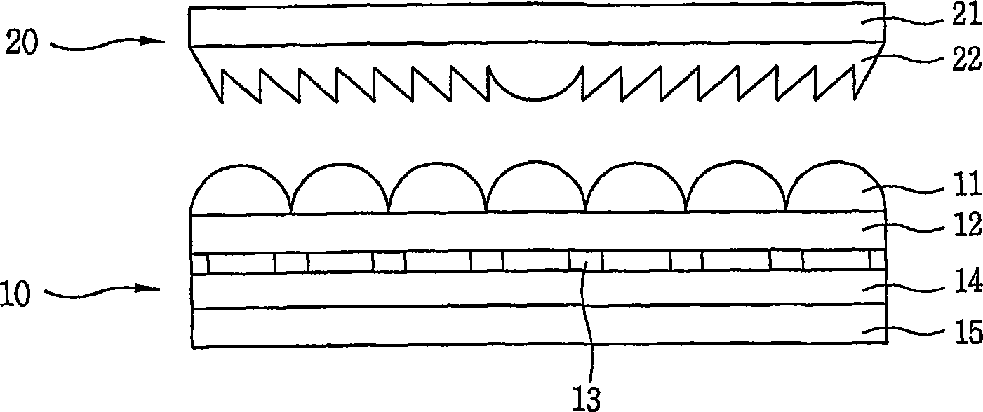
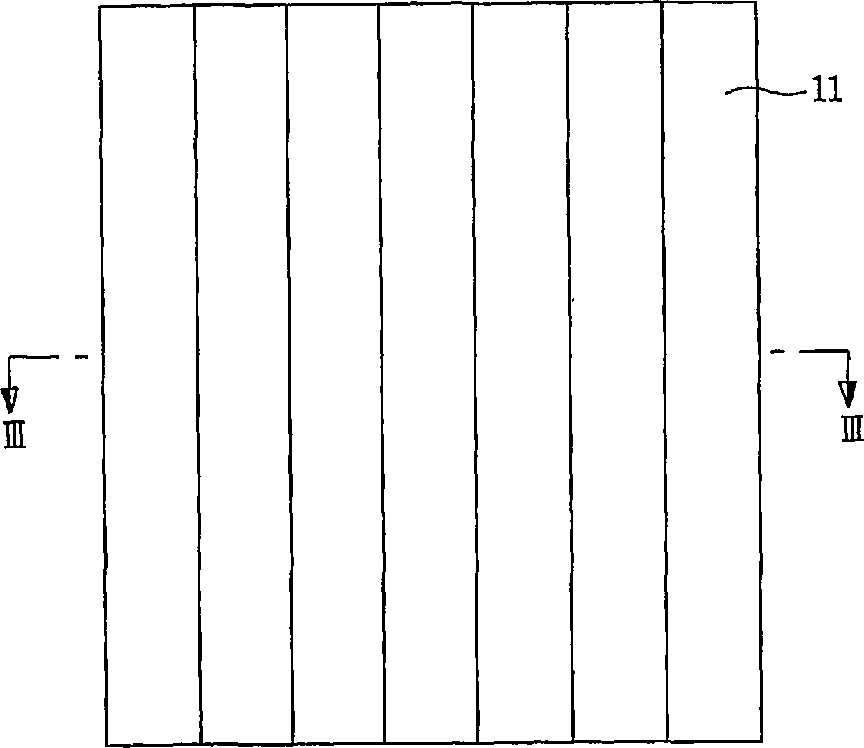
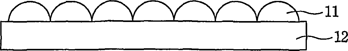
[0038] Figures 6 to 8 The figure shows an aspheric microlens array according to a preferred embodiment of the present invention. Image 6 ...


PUM


Abstract

An aspherical microlens arrays 100 comprise a base 120, and a plurality of aspherical microlens 110 arranged on the base 120 and having different curvature radiuse and conic coefficient respectively, along two orthogonal axes on the base 120 perpendicular to an optical axis, by which a degree of refraction, namely, a numerical aperture can be easily adjusted depending on each axial direction, a spherical aberration can be reduced, and concentration efficiency can be improved. In addition, in case of applying the aspherical microlens arrays 100 to a projection screen, an image sensor, or the like, it is advantageous to improve sensitivity and resolution thereof.

Description

technical field [0001] The present invention relates to aspheric microlens arrays, methods of manufacturing the same and applications using said aspheric microlens arrays, and more particularly to the ability to adjust in different ways by means of two orthogonal axes respectively along a plane perpendicular to the optical axis. An aspheric microlens array having improved alignment function and angular field of view through radius of curvature and conic coefficient, a manufacturing method thereof, and applications using the aspheric microlens array. Background technique [0002] In general, microlens arrays are often used in projection screens, which allow users to see big screen. In addition, the trend is that its field of application is gradually expanding. [0003] Figures 1 to 3 The figure shows one embodiment of a conventional microlens array applied to a projection screen. That is, figure 1 is a schematic diagram showing the structure of a conventional projection...

Claims


Application Information

Patent Timeline
Patent Type & Authority Applications(China)
IPC IPC(8): G02B3/04B29D11/00G02F1/1335H01L31/0232G02B3/00G02B3/02G03B21/62
CPCG02B3/0025G02B3/0018G02B3/0031G02B3/02G02B3/0056G02B3/04
Inventor 成东默朴纪垣李根雨李泳柱
Owner LG ELECTRONICS INC
Features
  • R&D
  • Intellectual Property
  • Life Sciences
  • Materials
  • Tech Scout
  • Unparalleled Data Quality
  • Higher Quality Content
  • 60% Fewer Hallucinations
Learn More