Radiation fan

A heat dissipation fan and fan frame technology, which is applied in the direction of electromechanical devices, electrical components, magnetic circuits, etc., can solve the problems of affecting the magnetic conduction area of ​​the stator and the winding space, and the inability to reduce the volume of the hub and the air intake of the heat dissipation fan.

Inactive Publication Date: 2007-02-07
FU ZHUN PRECISION IND SHENZHEN +1
View PDF0 Cites 10 Cited by
  • Summary
  • Abstract
  • Description
  • Claims
  • Application Information

AI Technical Summary

Problems solved by technology

However, the armature structure of the traditional stator is formed by stacking multiple stamped silicon steel sheets. The stator formed is a columnar structure. Along the axial direction of the stator, the cross-sectional size and shape of each point of the stator are basically the same, which not only affects the stator The magnetic conduction area and winding space are also limited by the shape of the stator. Without changing the size of the cooling fan, it is impossible to reduce the volume of the hub to increase the air intake of the cooling fan.

Method used


Image

  • Radiation fan
  • Radiation fan
  • Radiation fan

Examples


Embodiment Construction

[0022] Further description will be made below in conjunction with the embodiments with reference to the accompanying drawings.

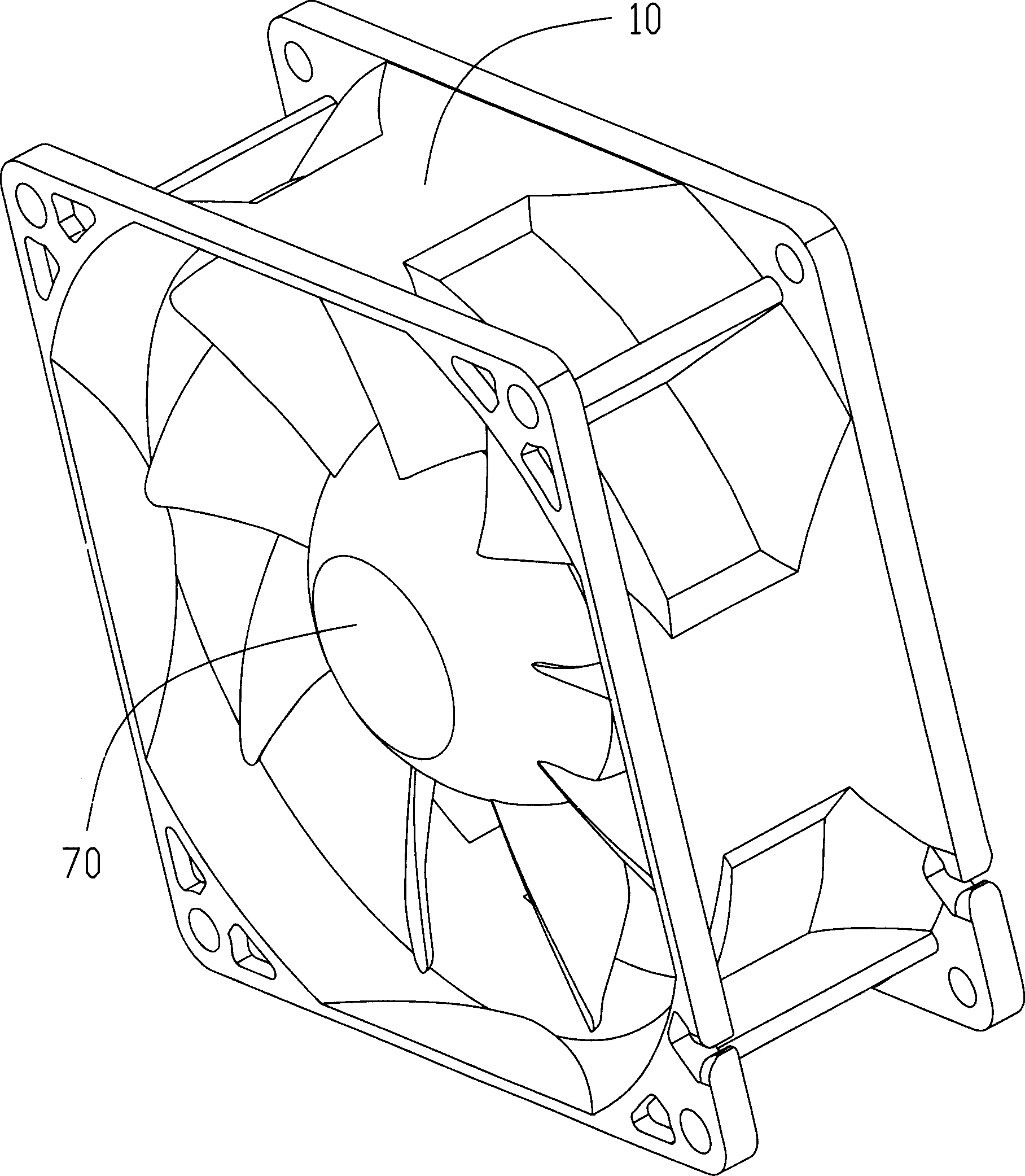
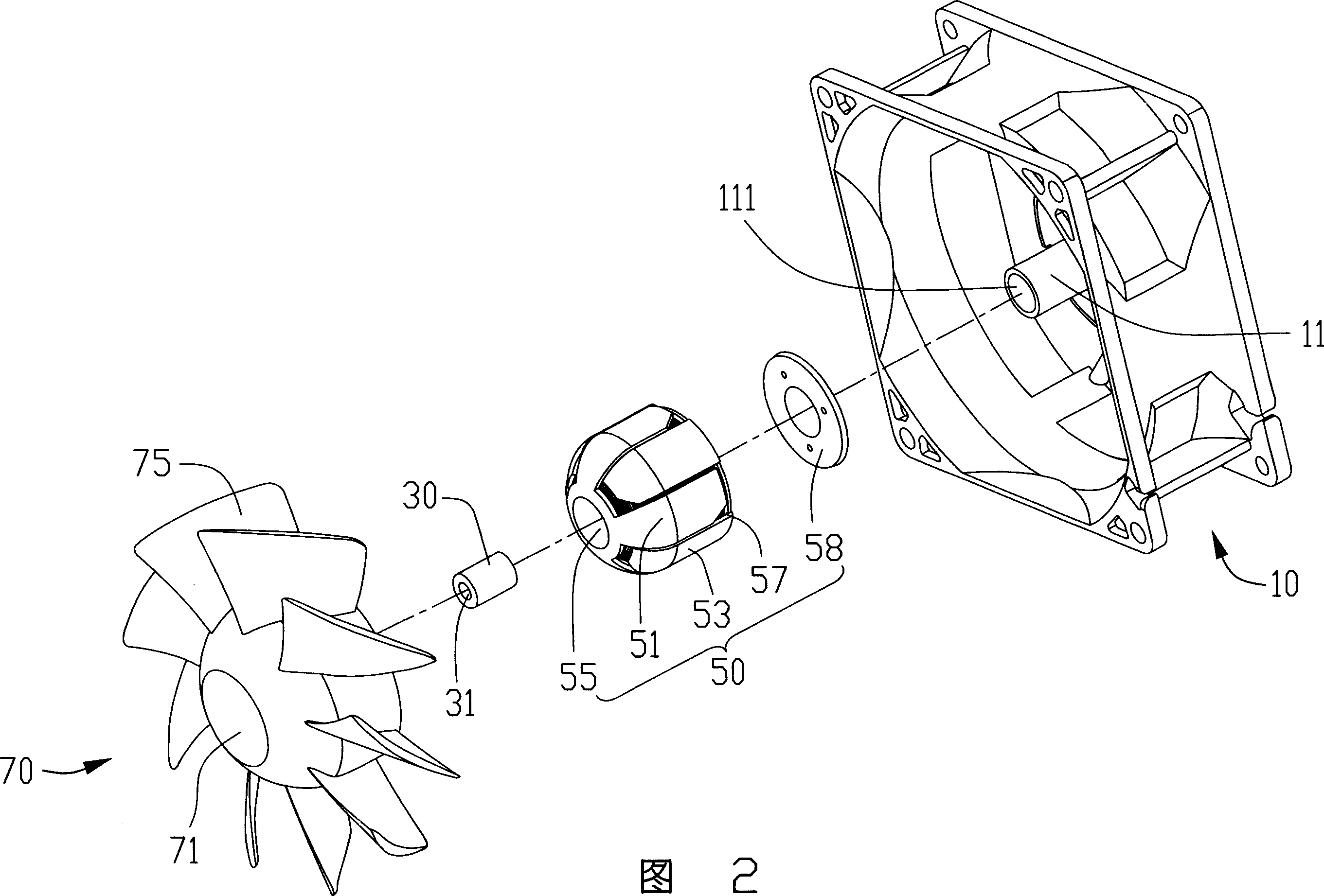
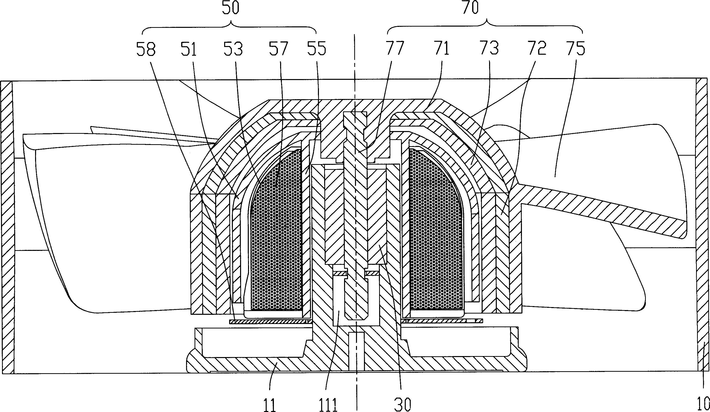
[0023] Such as Figure 1 to Figure 3 As shown, the cooling fan includes a fan frame 10 with a central column 11, a bearing 30 accommodated in the central column 11, a set of stator 50 set on the central column 11 and a rotor rotatably supported by the bearing 30 70.

[0024] A central column 11 protrudes upwards from the center of the fan frame 10 , and a central hole 111 is formed in the central column 11 for accommodating the bearing 30 . The bearing 30 includes a shaft hole 31 through which the rotor 70 passes. The fan frame 10 forms an air outlet corresponding to the bottom of the central column 11, and an air inlet is formed on the other side opposite to the air outlet.

[0025] Please also refer to Figure 4 and Figure 5 , the stator 50 is sleeved on the center column 11 of the fan frame 10, and the stator 50 forms a curved surface structu...


PUM


Abstract

The invention relates to a heat radiation fan, which comprises: a frame with middle cylinder, a bearing inside the middle cylinder, a stator sheathing the middle cylinder and a rotator rotationally supported by the bearing, wherein said fan has one wind inlet and one wind outlet; the stator comprises two magnetic pole plates and a hollow tube between two plates; said two plates both comprise one main body and several sheets extending from the edge of main body; the sheets form the expanding curvature structure near the wind inlet along the inlet wind direction, to increase the magnetic conductive area and the winding space, and reduce the hub volume, to improve the wind amount of fan.

Description

【Technical field】 [0001] The invention relates to a cooling fan structure, in particular to a cooling fan with a relatively large air intake. 【Background technique】 [0002] With the continuous advancement and wide application of large-scale integrated circuit technology, the heat consumed by electronic components such as CPU is getting higher and higher. In order to maintain the normal operation of electronic components, a heat sink is usually installed on the heat-generating electronic components. Install a cooling fan to provide forced airflow to assist cooling. [0003] Existing cooling fans such as Figure 13 As shown, it includes a fan frame 2 with a central column 22, a bearing 4 accommodated in the central column 22, a set of stator 6 set on the central column 22 and a rotor 8 rotatably supported by the bearing 4, The stator 6 includes a circuit board 62 and an armature 64 electrically connected to the circuit board 62. The armature 64 includes a plurality of stacke...

Claims


Application Information

Patent Timeline
Patent Type & Authority Applications(China)
IPC IPC(8): F04D29/54F04D29/32H02K1/27H02K1/14H02K1/02H02K3/00
CPCF04D25/0613F04D25/064H02K1/145F04D29/329F04D25/0646H02K7/14
Inventor 杨志豪童兆年游丰檀王琼媚侯春树刘泰健
Owner FU ZHUN PRECISION IND SHENZHEN
Why Eureka
Try Eureka