Branch pipe coupling and air conditioner provided with the same

A technology of pipe joints and branches, which is applied in the field of air-conditioning devices, can solve the problems of shortening the size of the branch and easy to generate bias flow, etc., and achieve the effect of reducing the size and ensuring the working space

Inactive Publication Date: 2007-02-07
DAIKIN IND LTD
View PDF0 Cites 5 Cited by
  • Summary
  • Abstract
  • Description
  • Claims
  • Application Information

AI Technical Summary

Problems solved by technology

However, when the T-shaped branch pipe 91 is arranged in the same horizontal branch arrangement as that of the Y-shaped branch pipe 81, that is, the T-shaped branch portion 92 of the T-shaped branch pipe 91 faces the horizontal direction, and the first branch nozzle portion 93 and The second branch nozzle part 94 is arranged at the same height, and at this time, the refrigerant flowing into the T-shaped branch pipe 91 from the confluence connection pipe or the branch connection pipe can also be branched in a substantially symmetrical direction with respect to the center line O-O of the inlet pipe part 82a. There is no height difference, however, in the T-shaped branch part 92, since there is no branch in a substantially symmetrical direction with respect to the center line O-O of the inlet pipe part 92a, it is easy to generate a bias flow.
[0011] It can be seen that no matter which of the above-mentioned existing Y-shaped branch pipes 81 and T-shaped branch pipes 91 is used as the pipe joint for branching, it is impossible to shorten the size near the branch part and prevent the flow deviation at the branch part at the same time.

Method used


Image

  • Branch pipe coupling and air conditioner provided with the same
  • Branch pipe coupling and air conditioner provided with the same
  • Branch pipe coupling and air conditioner provided with the same

Examples


Embodiment Construction

[0052] Hereinafter, a pipe joint for branching and an air conditioner having the pipe joint for branching according to an embodiment of the present invention will be described with reference to the drawings.

[0053] (1) Structure of pipe joint for branch

[0054] Figure 4 It is a figure explaining the structure of the branch pipe joint 181 in one Example of this invention.

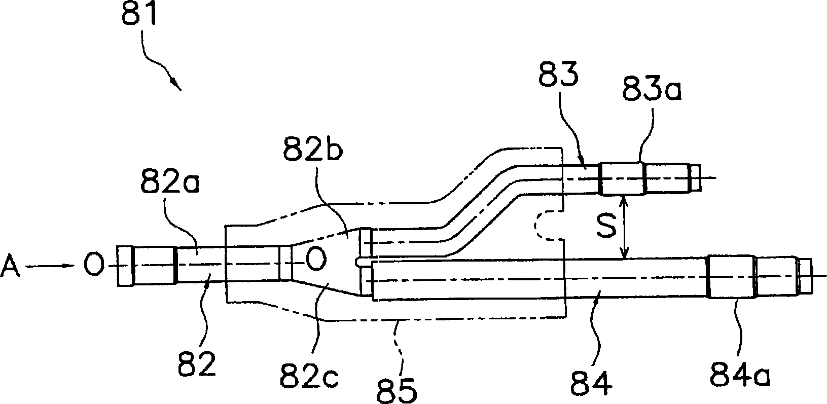
[0055] The branching pipe joint 181 has a substantially Y-shaped branching portion 182 , a first branching nozzle portion 183 , a second branching nozzle portion 184 , and a first divided pipe 186 .

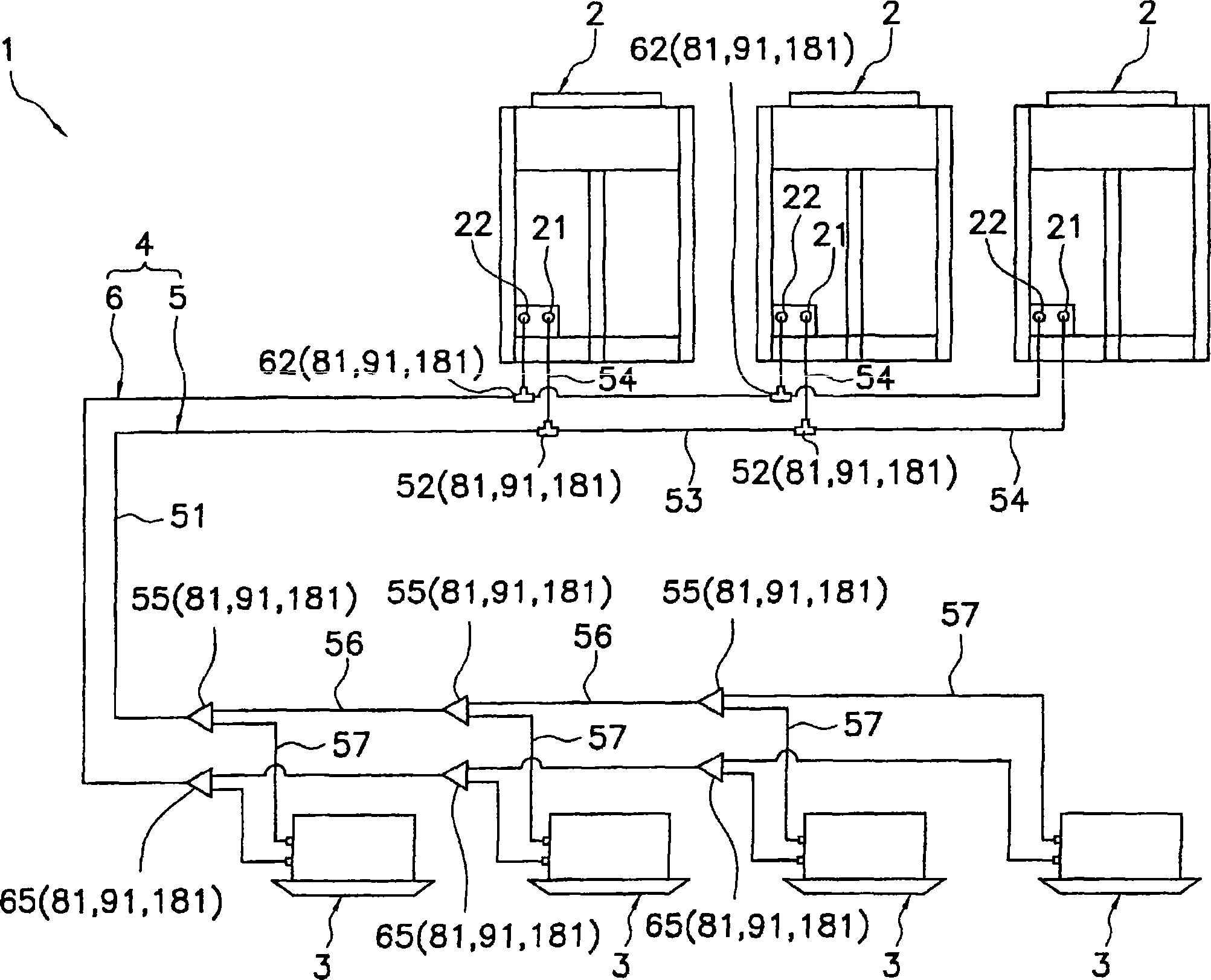
[0056] The branch portion 182 has the branch portion 82 with the existing Y-shaped branch pipe 81 (refer to figure 2 ) the same shape, with: inlet pipe portion 182a, the first outlet pipe portion 182b and the second outlet pipe portion 182c, the inlet pipe portion 182a from the main pipe (for example figure 1 The shown merging connection pipe 51 and the branch connection pipe 53) flow in the refrigerant...


PUM


Abstract

The present invention comprises a branching pipe joint, for distributing a refrigerant that flows within a main pipe to two flows, and an air conditioner provided therewith, and achieves both the compaction of the vicinity of the branch part and the prevention of drift therein. A branching pipe joint (181) comprises a substantially Y-pipe shaped branch part (182), a first branch nozzle part (183), a second branch nozzle part (184), and a first branch pipe (186). The first branch pipe (186) is a pipe member, wherein one end part is connected to a tip part of the first branch nozzle part (183) during plumbing work. The first branch nozzle part (183) and the second branch nozzle part (184) are disposed so that a spacing between a portion of the tip part of the first branch nozzle part (183) nearest the second branch nozzle part (184) side and a portion of the second branch nozzle part nearest the tip part of the first branch nozzle part is less than or equal to 40 mm.

Description

technical field [0001] The present invention relates to a pipe joint for branching and an air conditioner having the pipe joint for branching. Background technique [0002] In conventional air conditioners, an outdoor unit and an indoor unit are connected by connection pipes such as gas refrigerant connection pipes and liquid refrigerant connection pipes, thereby constituting a so-called stand-alone air conditioner. Such air conditioners 1 such as figure 1 As shown, or a plurality of indoor units 3 ( figure 1 4 units in the middle), the connecting pipe 4 is branched so that the refrigerant can be distributed from the connecting pipe 4 to each indoor unit 3, or a plurality of outdoor units 2 ( figure 1 3 units in the middle), connecting piping 4 ( figure 1 In the figure, the gas refrigerant connection pipe 5 and the liquid refrigerant connection pipe 6) are branched so that the refrigerant can be distributed from the connection pipe 4 to each outdoor unit 2. [0003] Next...

Claims


Application Information

Patent Timeline
Patent Type & Authority Applications(China)
IPC IPC(8): F25B41/00F25B13/00
CPCF25B41/003F25B2500/01F25B41/42F25B41/00F25B13/00
Inventor 竿尾忠水谷和秀大仓悟
Owner DAIKIN IND LTD
Why Eureka
Try Eureka