
Motionless lens systems and methods

A lens, lens technology, applied in the parts, lenses, instruments, etc. of TV systems, can solve the problem of moving one or more lens parts, etc.

Inactive Publication Date: 2007-02-14
因·S·唐
View PDF2 Cites 31 Cited by
  • Summary
  • Abstract
  • Description
  • Claims
  • Application Information

AI Technical Summary

Problems solved by technology

[0004] A disadvantage of conventional zoom lenses is that they are generally large and heavy, making it difficult to fit a zoom lens into a small device {eg, a mobile phone, a personal digital assistant (PDA), or a pocket camera}
Another disadvantage of conventional zoom lenses as well as autofocus lenses in general is that one or more lens parts must be moved (e.g., mechanically repositioned within the lens group) to change the focal length, which typically requires space and energy to accommodate this move

Method used


Image

  • Motionless lens systems and methods
  • Motionless lens systems and methods
  • Motionless lens systems and methods

Examples


Embodiment Construction

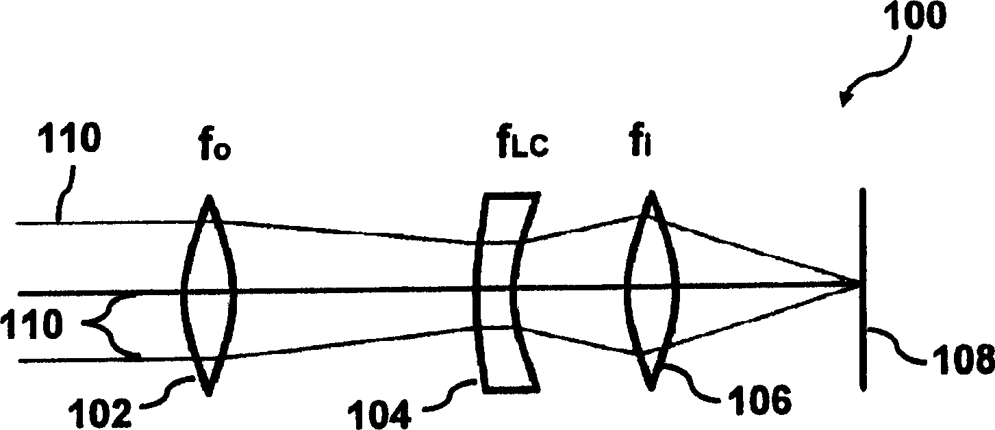
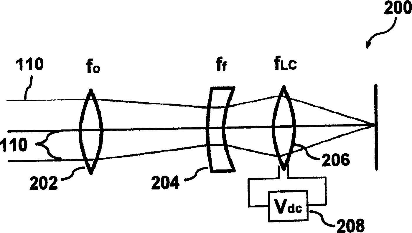
[0031] figure 1 A lens 100 according to an embodiment of the present invention is shown. The lens 100 includes an objective lens 102 , an adjustable field lens 104 , and an imaging lens 106 . Objective lens 102 (with f o Indicated) and imaging lens 106 (with f i denoted) may be a conventional objective lens and a conventional image lens (also referred to as an imaging lens or an eyepiece), respectively, which may be made of glass, plastic, or other known conventional lens materials.

[0032] The imaging lens 106 can be positioned away from, adjacent to, or shaped as an adjustable field lens 104 (with f LC Indicates part of). As will be described in further detail herein, the tunable field lens 104 is a lens whose refractive index is varied, for example, by applying a voltage to the tunable field lens 104 . By changing the refractive index of the tunable field lens 104, the focal length or focal point of the lens 100 can be changed.

[0033] As an example, such as figure...


PUM


Abstract

Systems and methods are disclosed herein to provide zoom and / or autofocus lenses. The lens comprises: a first lens comprising of a nematic liquid crystal which is adapted to provide a variable index of refraction; and a second and a third lens, wherein the first lens, the second lens, and the third lens are situated in the fixed positions to provide a focal length for the lens, with a variable focus based on the index of refraction of the first lens. In accordance with an embodiment of the present invention, the lens is provided with at least one tunable lens. The focal length and / or focus of the lens may be varied without mechanically moving or changing the separation between one or more lens components. The method of the invention comprises: providing a first lens with a variable index of refraction; providing at least one second lens situated in fixed positions; and changing the index of refraction of the first lens to adjust the focus of the fixed lens.

Description

technical field [0001] The present invention relates generally to optical devices, and more particularly to lenses, such as lenses for zoom and autofocus applications. [0002] This application is a partial continuation application of the U.S. Patent Application No. 10 / 797,809 filed on March 9, 2004, entitled "Lens Array and Method of Making Same", and the serial number, the entire contents of which are incorporated as the present application refer to. Background technique [0003] The role of zoom and autofocus lenses is well known, and they are used for many different purposes. For example, a conventional zoom lens (ie, any type of lens with variable focal length) may include at least two lens components, the shape and spacing of which determine the focal length of the zoom lens. As an example, a zoom lens for mechanical compensation in a camera typically accommodates the movement of the two parts so that the image position or imaging plane remains constant. As another ...

Claims


Application Information

Patent Timeline
IPC IPC(8): G02B15/16G02F1/13G02B3/00
CPCG02F2203/28G02B3/0031H01L27/14627G02B3/0056G02F1/133371G02F1/29G02B3/0043H04N5/23212G02B3/0012H04N23/55H04N23/67G02B3/14G02B3/12
Inventor 因·S·唐
Owner 因·S·唐
Learn More