Contact for cable connection and cable connecting method using the contact

A cable and contact technology, applied in the field of contact structure, can solve the problems of long time-consuming, difficult to design sufficient terminal length, and insufficient guarantee of the length of the tapered surface 4, etc.

Inactive Publication Date: 2007-02-14
SMK CO LTD
View PDF2 Cites 2 Cited by
  • Summary
  • Abstract
  • Description
  • Claims
  • Application Information

AI Technical Summary

Problems solved by technology

[0010] Also, will Figure 8 When the structure shown above is used for a cable equivalent to AWG42, the overall size becomes smaller, so the terminal width at the cutout portion becomes narrower, and it is difficult to design a sufficient terminal length at the cutout portion due to the need for narrower pitches or miniaturization.
As a result, the length of the tapered surface 4 cannot be sufficiently ensured, so there is a possibility that the insulator of the cable will not be scratched by the tapered surface 4
[0011] In addition, the cable equivalent to AWG42 is thinner overall, so there is a possibility that the terminal cannot be fully pressed
Due to the above-mentioned problems, welding is currently used to connect such ultra-thin cables, but it takes a long time and has the disadvantage of poor workability.

Method used


Image

  • Contact for cable connection and cable connecting method using the contact
  • Contact for cable connection and cable connecting method using the contact
  • Contact for cable connection and cable connecting method using the contact

Examples


Embodiment 1

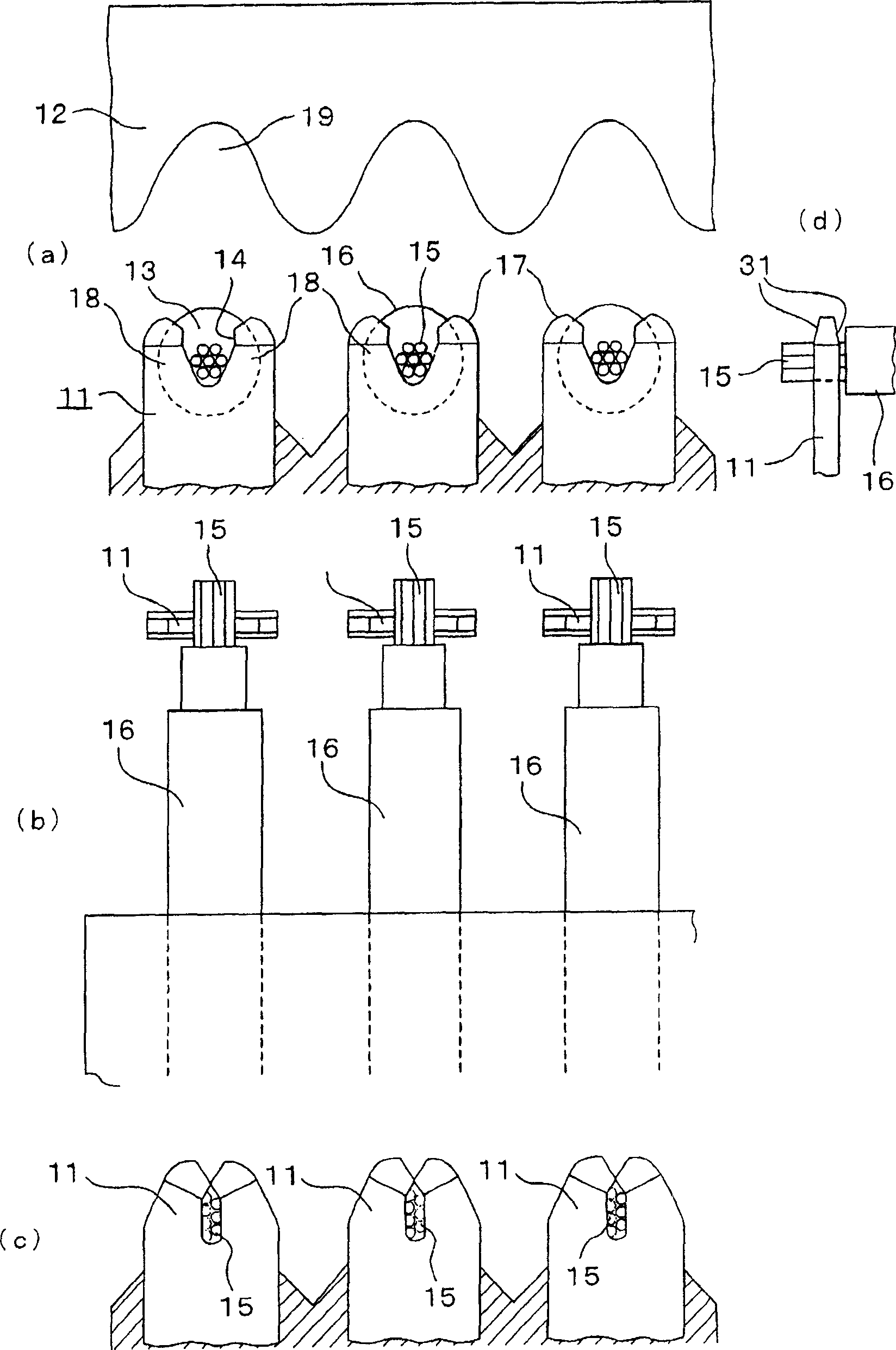
[0043] according to Figure 1~4 Examples of the present invention will be described. The cable connection contact of the present invention is characterized in that it can also be applied to the case of using an ultra-thin cable. In the following description, the AWG42 equivalent to using 7 core wires each with a diameter of 0.025mm is used. The case of an ultra-thin cable will be described as an example.

[0044] figure 1 (a) shows the contact 11 for cable connection of this invention, and the punching part 12 used for crimp connection of the contact 11 for cable connection. This cable connection contact 11 is provided with a notch 13 at the center of the upper part of the terminal having a plate thickness of about 0.1 mm. considerable length) large. For example, in the cable 16 using seven core wires 15 each having a diameter of 0.025 mm, the length corresponding to the diameter of the core wire 15 is about 0.075 mm, but in the case of the contact corresponding to the ca...

Embodiment 2

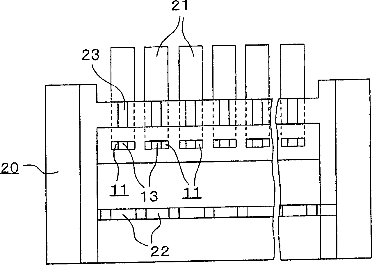
[0051] In the foregoing embodiments, only the structure of the contact 11 is described, but in this embodiment 2, the figure 2 as well as Figure 4 The illustrated example is one in which the contacts 11 are arranged in the housing 20 .

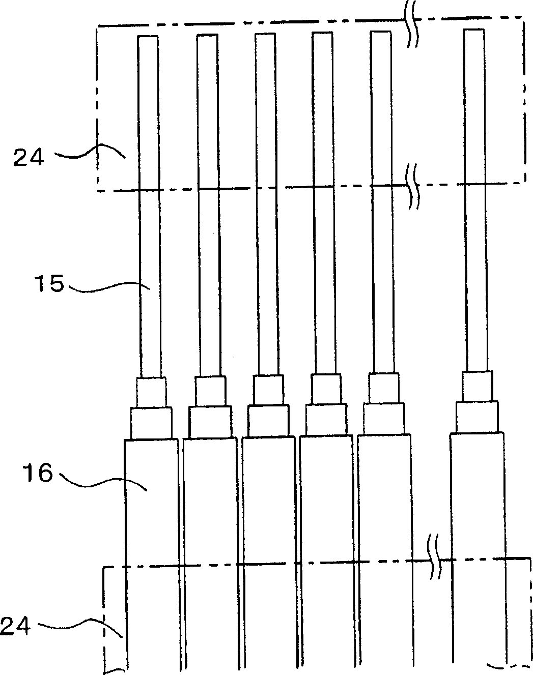
[0052] Such as figure 2 as well as Figure 4 As shown, a plurality of contacts 11 for connecting a plurality of cables 16 are arranged side by side in the housing 20, and these contacts 11, such as Figure 4 The shown configuration is bent into an L-shape, and is installed by inserting the front end portion of the contact 11 from the back surface of the case 20, and the other side of the bend is arranged at the bottom of the case as a base end portion 21 for connection to a circuit board or the like. rear side. Also, the cable support portion 22 for supporting the cable portion covered by the sheath and the core wire support portion 23 for supporting the core wire 15 are provided so that they can be easily carried out when the cable 16 ...

Embodiment 3

[0057] In the preceding examples, if figure 1 As shown in (a), the shape of the notch 13 of the contact 11 is formed to have a straight line 14 cut in the vertical direction from the top, and a V-shape is formed at a position deeper than the straight line 14 . However, the present invention is not limited thereto, for example, it may also be as Figure 5 (a) Contact 26 of the shape shown.

[0058] Should Figure 5 The contact 26 shown in (a) forms a notch 27 in the center and uses both sides of the notch as a crimping terminal 30, and the upper side of the crimping terminal 30 is formed as a tapered surface 28 (or formed as arc-shaped), and figure 1 Like the contact 11 shown in (a), the deep position of the notch portion 27 is formed into a V shape, but the upper part of the portion formed in such a V shape is not formed as a straight line cut in the vertical direction, but is formed with a The inclined portion 29 is inclined such that the upper opening portion is narrow...


PUM


Abstract

The invention provides a cable connecting contact and a method for connecting a cable using the contact capable of wiring certainly even if the cable is of very thin type, and of enhancing the productivity of terminals. The contact to generate electric connection through pressure attachment with the core part of the cable formed by covering one or more core wires consisting of conductor with an insulating material is provided with an opening in the center of the end face of a metal member in plate shape and a slit shaped as a groove with the width narrowing gradually in a position deeper than the opening, in which the two sides where the slits are formed serve as crimp terminals.

Description

technical field [0001] The present invention relates to a structure for a contact capable of conducting a cable having an elastically deformable sheath by crimping or the like. Background technique [0002] Conventionally, a connection method has been used in which a cable having an elastically deformable sheath can be electrically connected by crimping or the like. For example there are pairs with Figure 8 The terminal 1 with the sharp notch 3 shown in (a) is press-fitted into the cable 2 formed by covering the sheath of the cable conductor with an insulator to electrically conduct it. exist Figure 8 In (a), the width of the tip part of the terminal 1 is formed wider than the diameter of the cable, but the central groove part is formed narrower than the diameter of the core wire inside the cable, and the section from the tip to the groove is formed as a tapered surface 4 (according to the situation, it also forms a blade shape), so when pressing the cable, use the sharp ...

Claims


Application Information

Patent Timeline
Patent Type & Authority Applications(China)
IPC IPC(8): H01R4/24
Inventor 富樫晃司
Owner SMK CO LTD
Why Eureka
Try Eureka