Connector for cold cathode tube

A cold cathode and connector technology, which is applied to devices for connecting, joining/disconnecting connecting components, discharge tubes, etc., can solve the problems of lengthening electrode wires, bending and deformation of electrode wires, complicated structure of connecting terminals, etc., and achieves safe clamping Easy to maintain and install

Inactive Publication Date: 2007-06-20
NIPPON TANSHI CO LTD
View PDF3 Cites 1 Cited by
  • Summary
  • Abstract
  • Description
  • Claims
  • Application Information

AI Technical Summary

Problems solved by technology

[0012] In the prior art including these patent documents, for example, in the case of Patent Document 1, there is the following problem to be solved: due to the connection terminal of the connector, the electrode wire bent into an L-shape must be crimped. Therefore, it is necessary to lengthen the electrode wire, which cannot be used in a short case; an L-shaped bending process is required; since the front end side of the electrode wire is inserted through the through hole of the connector and the connection terminal, the electrode wire The insertion work is very troublesome, and there is also the possibility of bending during insertion; because it is a structure that rotates the actuator, it is very large; the internal connection status cannot be confirmed; it is not easy to apply to the lead type, etc.
[0013] In addition, in the case of Patent Document 2, there is a problem to be solved as follows: since the contact is opened by the cam part against the pressure of the elastic force, the structure of the connection terminal is very complicated and it is difficult to carry out. Mass production, at the same time, is enlarged due to the structure that makes the actuator rotate; the assembly of the connector is not easy; it is difficult to apply to the lead type, etc.
[0014] In addition, in the case of Patent Document 3, there are the following problems to be solved: Since the electrode wire is inserted between the contact parts having elastic force, a large insertion force is required; Possibility of reliable connection; unable to confirm internal connection status; not easy to apply to substrate mount type, etc.
[0015] In addition, in the case of Patent Document 4, there is the following problem to be solved: Since the core wires of the electrode wire and the lead wire need to be provided at two positions respectively, the assembling work at the time of mass production is very complicated. Insert both the electrode wire and the core wire of the lead wire between the contact parts with elastic force at the same time, so a large insertion force is required; at the same time, if the two sides cannot be pressed and inserted equally, there will be bending deformation of the electrode wire, which cannot Possibility of reliable connection; not easy to apply to substrate mount type etc.

Method used


Image

  • Connector for cold cathode tube
  • Connector for cold cathode tube
  • Connector for cold cathode tube

Examples


Embodiment Construction

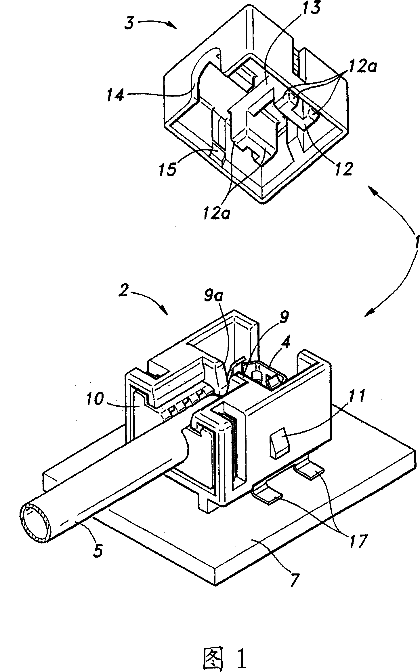
[0081] The connector for cold cathode fluorescent tubes according to the present invention will be described in detail based on the drawings showing the best mode to which the present invention is applied. FIGS. 1 to 6 show a first embodiment applied to a board-mounted type for connecting a connection terminal to a printed circuit board. 7 to 8 show modifications of the first embodiment applied to the substrate mount type. 9 to 13 show a second embodiment of the lead wire type applied to connecting the connection terminal to the lead wire. 14 to 16 show modifications of the second embodiment applied to the lead type.

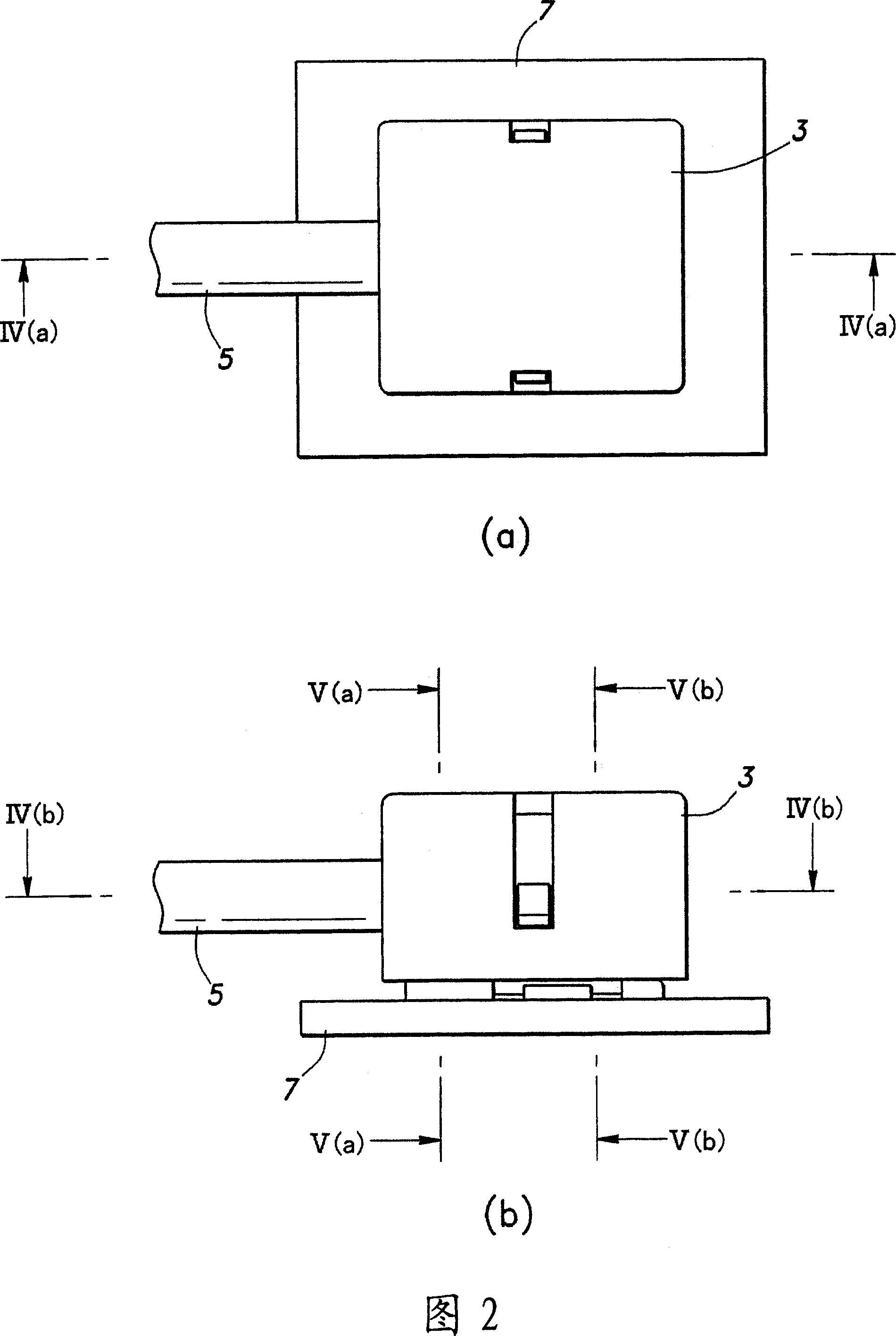
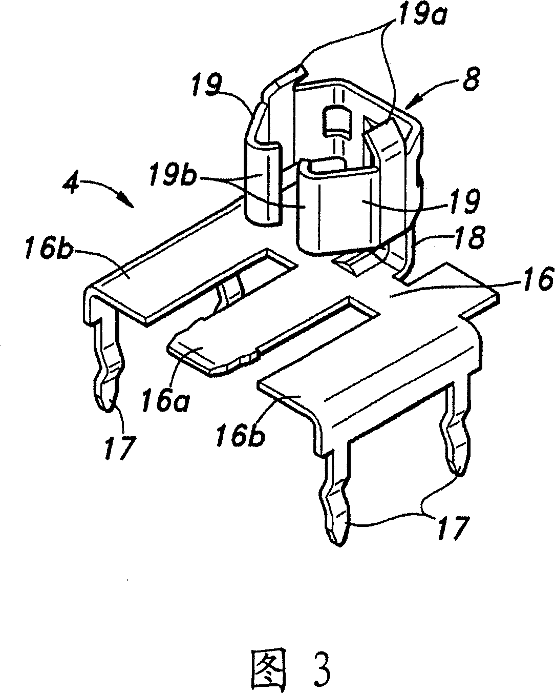
[0082] The first embodiment will be described. FIG. 1 is a perspective view showing a CCFL connector 1 mounted on a substrate before a top cover is mounted. Fig. 2 shows the state after the top cover is attached, (a) is a plan view, and (b) is a side view. FIG. 3 is a perspective view showing a connection terminal built in the CCFL connector 1 . Fig. 4 is a ...


PUM


Abstract

The present invention provides a connector for cold cathode fluorescent tube, which can dispose cold cathode fluorescent tube and electrode line, and can execute connection reliably even the electrode line has deviation without insert force and bending distortion, the connection can be executed easily, making the connector to minitype, the inner connecting status can be affirmed by eyes and the connection can be reliably executed, the connector can be easily applied to substrate fitting mode and guide lines mode. The case of the connector is formed by the casing (2) and top cover (3), a keep chamber for cold cathode and a connection chamber for receiving connection terminals (4) are disposed in the case, a pair of activation cards (19) with crimping part in the front side is disposed on the contact point (8), the electrode line (6) can be inserted between each activation card (9) with a wedging status when the top part of the cold cathode fluorescent tube (5) is fit into the keep chamber, a top cover having a pair of action doming (12) are covered on the opening part of the case, the activation cards (19) of the contact point (8) are pressed from outside, the electrode line (6) is clamped and crimped by the crimping part.

Description

technical field [0001] The present invention relates to a connector for cold cathode fluorescent tubes, which is used in a case where, for example, an end portion of a cold cathode fluorescent tube (CCFL) is mainly used in a backlight of a liquid crystal display device, etc., is held by a connector , At the same time, the electrode wire (also known as dumet-coated copper-iron-nickel alloy wire, etc.) is connected to the contact of the connection terminal accommodated in the connector, and connected to the power supply side through the connection terminal. Background technique [0002] Compared with hot-cathode tubes such as fluorescent lamps for general lighting, which are also fluorescent tubes, cold-cathode fluorescent tubes can have a very thin shape due to their simple electrode structure, and can be used as backlights for various electronic devices that perform liquid crystal displays. (Back lighting) is widely used. Unlike fluorescent lamps for general lighting, the wi...

Claims


Application Information

Patent Timeline
Patent Type & Authority Applications(China)
IPC IPC(8): H01R33/08H01R13/62
CPCH01J61/36H01R33/05H01R33/97
Inventor 榎本真也藤野优
Owner NIPPON TANSHI CO LTD
Why Eureka
Try Eureka