Heavy-current electronic switch of static and dynamic flow equalization

An electronic switch and high current technology, which is applied in the direction of electronic switches, electrical components, pulse technology, etc., can solve the problems of inconsistent parameters, inconsistent branch current and voltage, burned components, etc., and achieves convenient installation and replacement, simple and reliable structure, Solve the effect of dynamic current sharing

Inactive Publication Date: 2007-02-14
INST OF PLASMA PHYSICS CHINESE ACAD OF SCI
View PDF0 Cites 4 Cited by
  • Summary
  • Abstract
  • Description
  • Claims
  • Application Information

AI Technical Summary

Problems solved by technology

[0002] At present, the main body of the known high-current electronic switch mainly uses the parallel connection of power electronic devices to achieve the purpose of outputting high current, but the installation of the power electronic devices is arranged side by side. Because the parameters of each component are inconsistent, its structure cannot be guaranteed at all. The current consistency of each branch cannot guarantee

Method used


Image

  • Heavy-current electronic switch of static and dynamic flow equalization
  • Heavy-current electronic switch of static and dynamic flow equalization

Examples


Embodiment Construction

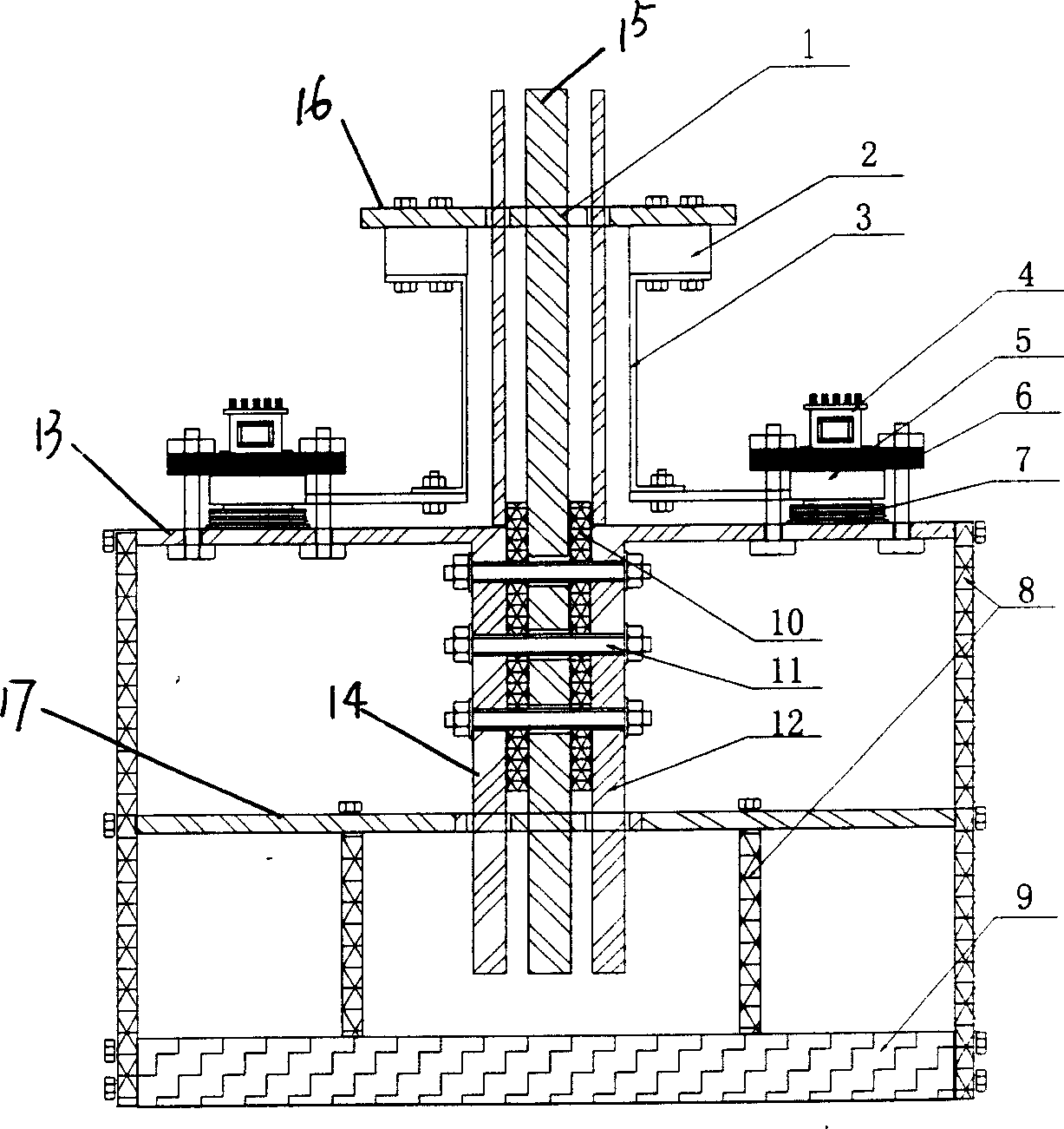
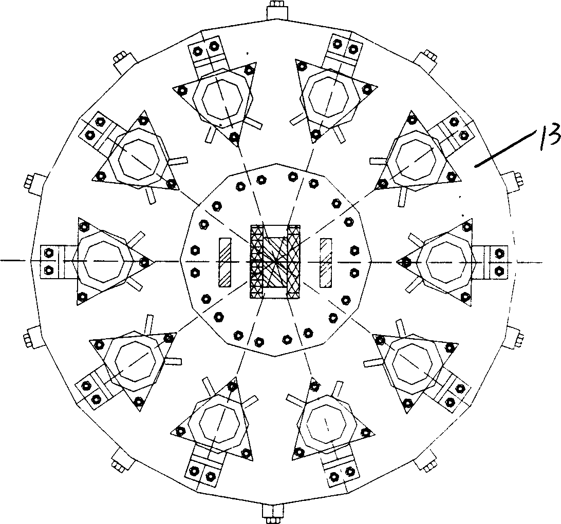
[0018] See attached picture.

[0019] Static and dynamic current sharing high-current electronic switch, including positive busbar 12, negative busbar 1, thyristor 7, positive busbar 12 is composed of positive conductive plate 13 and two positive plates 14, positive conductive plate 13 has a hole in the center , two parallel positive plates 14 are respectively connected to the edge of the hole, the positive conductive plate 13 is installed on the chassis 9 through the insulating bracket 8; the negative busbar 1 is installed between the positive plates 14, and the negative busbar 1 is formed by the negative pole plate 15 and a negative electrode conductive plate 16, the negative electrode conductive plate 16 is located at the upper end of the negative electrode plate 15 and perpendicularly intersects with it, between the negative electrode plate 15 and the positive electrode plate 14 is an insulating spacer 10, which is fixed by a screw 11, and the two positive electrode plates ...


PUM


Abstract

This invention discloses a large current electronic switch equalizing in static and dynamic state including a positive bus, a negative bus and thyristors, in which, the positive bus is composed of a positive conduction plate and two positive boards, the negative bus is composed of a negative board and a conduction plate, multiple pairs of thyristors are symmetrically mounted on the positive plate radially, water-cooling plates are mounted on the thyristors with insulation clamp boards set on the positive conduction plate, thyristor triggers are mounted on the clamp boards, quick fuses in the same number to the thyristors are mounted uniformly on the bottom of the negative conduction plate and water-cooling resistors are set between the quick fuses and the corresponding water-cooling plates.

Description

technical field [0001] The invention relates to a high-current device, in particular to a high-current electronic switch current equalizer. technical background [0002] At present, the main body of the known high-current electronic switch mainly uses the parallel connection of power electronic devices to achieve the purpose of outputting high current, but the installation of the power electronic devices is arranged side by side. Because the parameters of each component are inconsistent, its structure cannot be guaranteed at all. The current consistency of each branch cannot guarantee the dynamic balance of the current of each branch. The mutual interference between the main circuit busbars, between the branches, and between the busbars and the branches is inconsistent. The mutual influence state of the electronic switch is inconsistent, which leads to the current and voltage of each branch at the moment when the electronic switch is turned on and off, and the current and vo...

Claims


Application Information

Patent Timeline
IPC IPC(8): H03K17/00
Inventor 汤伦军李定付鹏
Owner INST OF PLASMA PHYSICS CHINESE ACAD OF SCI
Why Eureka
Try Eureka