Braking force generator for a hydraulic vehicle braking system

A technology of hydraulic braking and braking force, applied in the direction of braking safety systems, brakes, braking transmission devices, etc., can solve the problems of increased manufacturing costs, large equipment costs, etc., and achieve the effect of improving vulnerability

Inactive Publication Date: 2007-02-14
LUCAS AUTOMOTIVE GMBH
View PDF2 Cites 8 Cited by
  • Summary
  • Abstract
  • Description
  • Claims
  • Application Information

AI Technical Summary

Problems solved by technology

However, there are already known braking systems which, in order to ensure a reliable braking operation even in the event of a failure of the braking force generating device, are relatively expensive to manufacture and entail considerable equipment outlays

Method used


Image

  • Braking force generator for a hydraulic vehicle braking system
  • Braking force generator for a hydraulic vehicle braking system
  • Braking force generator for a hydraulic vehicle braking system

Examples


Embodiment Construction

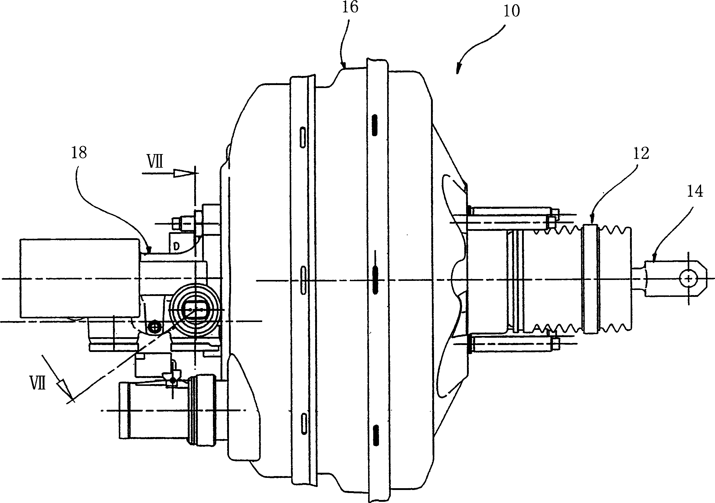
[0038] exist figure 2 In , the brake force generator according to the invention is shown in side view and is indicated as a whole by the reference number 10 . The brake force generator comprises an actuation unit 12 into which a force input element 14 is introduced. Force input element 14 can be connected with brake pedal ( figure 2 not shown) connected. The actuation unit 12 is connected to the chamber structure 16 . Part of the cylinder housing 18 of the master cylinder is visible on the side of the chamber structure 16 facing away from the actuating unit 12 .

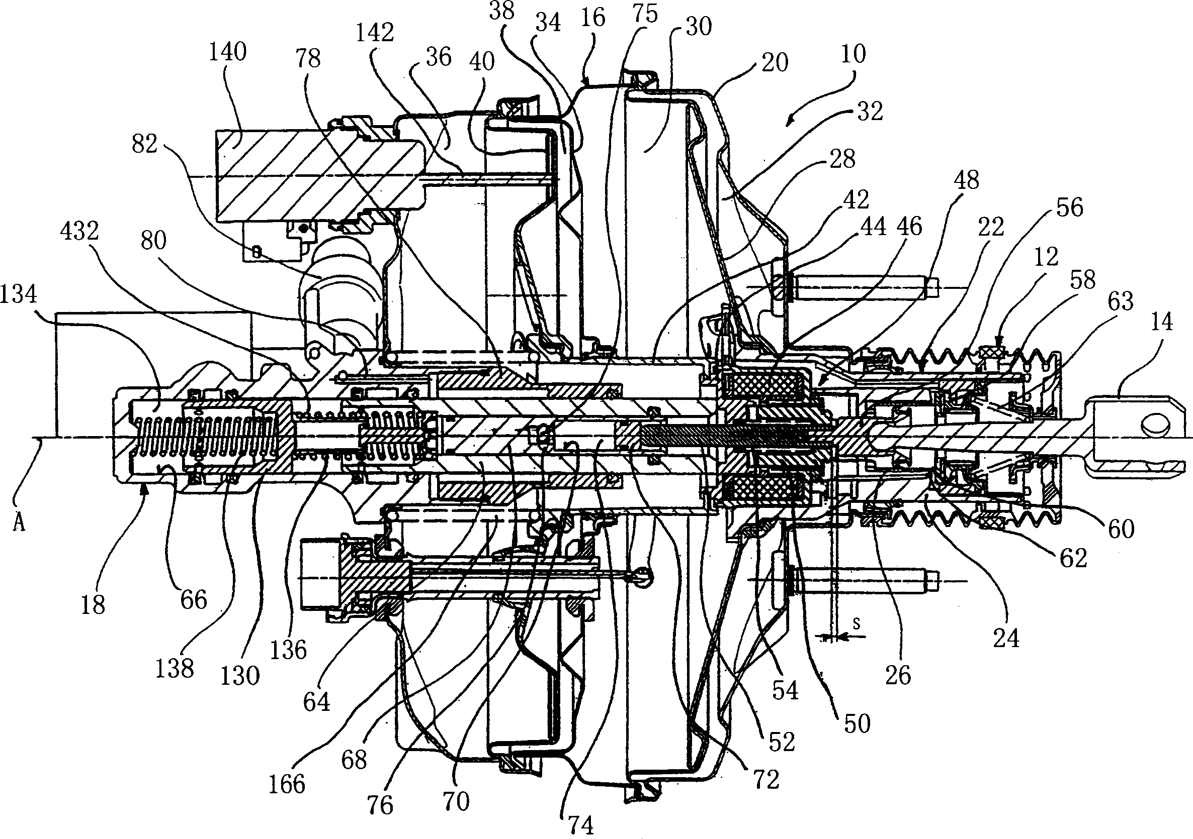
[0039] In order to describe in detail the structure of the braking force generator 10 according to the present invention, refer to image 3 . The basic structure of the brake force generator 10 according to the invention consists of two modules, namely: on the one hand the cylinder housing 18 and on the other hand the brake force generator housing 20 into which the cylinder housing 18 is inserted. body 20 and...


PUM


Abstract

The invention relates to a braking force generator (10), for a hydraulic vehicle braking system, comprising a force introduction member (14), which is or may be coupled to a brake pedal (P) and which may be mounted in a base housing of the brake force generator (10), a main brake cylinder, in which a primary piston (64), for generation of a hydraulic braking pressure, runs in a displaceable manner, a pedal counter-force simulation device (106), coupled to the force introduction member (14), a pedal operation recording device (150), for recording a pedal operation and an operation force generation device, for exerting an operating force on the primary piston (64), whereby the operating force generation device comprises a control valve (22), a chamber arrangement (16) and an electromagnetic actuator (48). The chamber arrangement (16) is embodied with a vacuum chamber (30) and a working chamber (32), separated from the vacuum chamber (30) by a moving wall (28), in fluid connection to each other by means of the control valve (22) and the control valve (22) is operated according to the recorded pedal operation.

Description

technical field [0001] The invention relates to a brake force generator having: a force input element connectable or connected to a brake pedal and movable in the basic housing of said brake force generator; a master cylinder, a master piston Guided movably therein, wherein said master piston and said master cylinder define a master pressure chamber for generating hydraulic brake pressure; a pedal reaction force simulation device connectable to said force input element; for pedal actuation detecting means for detecting pedal actuation; and actuation force generating means for generating an actuation force acting on said master piston. Background technique [0002] In current conventional braking systems, the hydraulic brake pressure required to act on the wheel brakes of the vehicle is mainly generated by the master cylinder. To this end, it is necessary to introduce an actuation force on said master cylinder that is generated in response to brake pedal actuation by the dri...

Claims


Application Information

Patent Timeline
Patent Type & Authority Applications(China)
IPC IPC(8): B60T8/40B60T13/57B60T13/72B60T7/04B60T8/32B60T13/563B60T17/18
CPCB60T8/4077B60T7/042B60T13/563B60T13/57B60T17/18
Inventor 彼得·施吕特
Owner LUCAS AUTOMOTIVE GMBH
Why Eureka
Try Eureka