Transmitting/receiving apparatus and transmitting/receiving method

一种接收装置、发送权的技术,应用在空间发射分集、基带系统零部件、多路复用通信等方向,能够解决判断不正确、传输效率下降等问题,达到提高传输效率的效果

Inactive Publication Date: 2007-02-14
OPTIS WIRELESS TECH LLC
View PDF3 Cites 3 Cited by
  • Summary
  • Abstract
  • Description
  • Claims
  • Application Information

AI Technical Summary

Problems solved by technology

[0011] As mentioned above, in the existing device, there is an incorrect judgment on whether to carry out space division multiplexing communication through directivity control, which leads to transmission efficiency. falling problem

Method used


Image

  • Transmitting/receiving apparatus and transmitting/receiving method
  • Transmitting/receiving apparatus and transmitting/receiving method
  • Transmitting/receiving apparatus and transmitting/receiving method

Examples


Embodiment approach 1

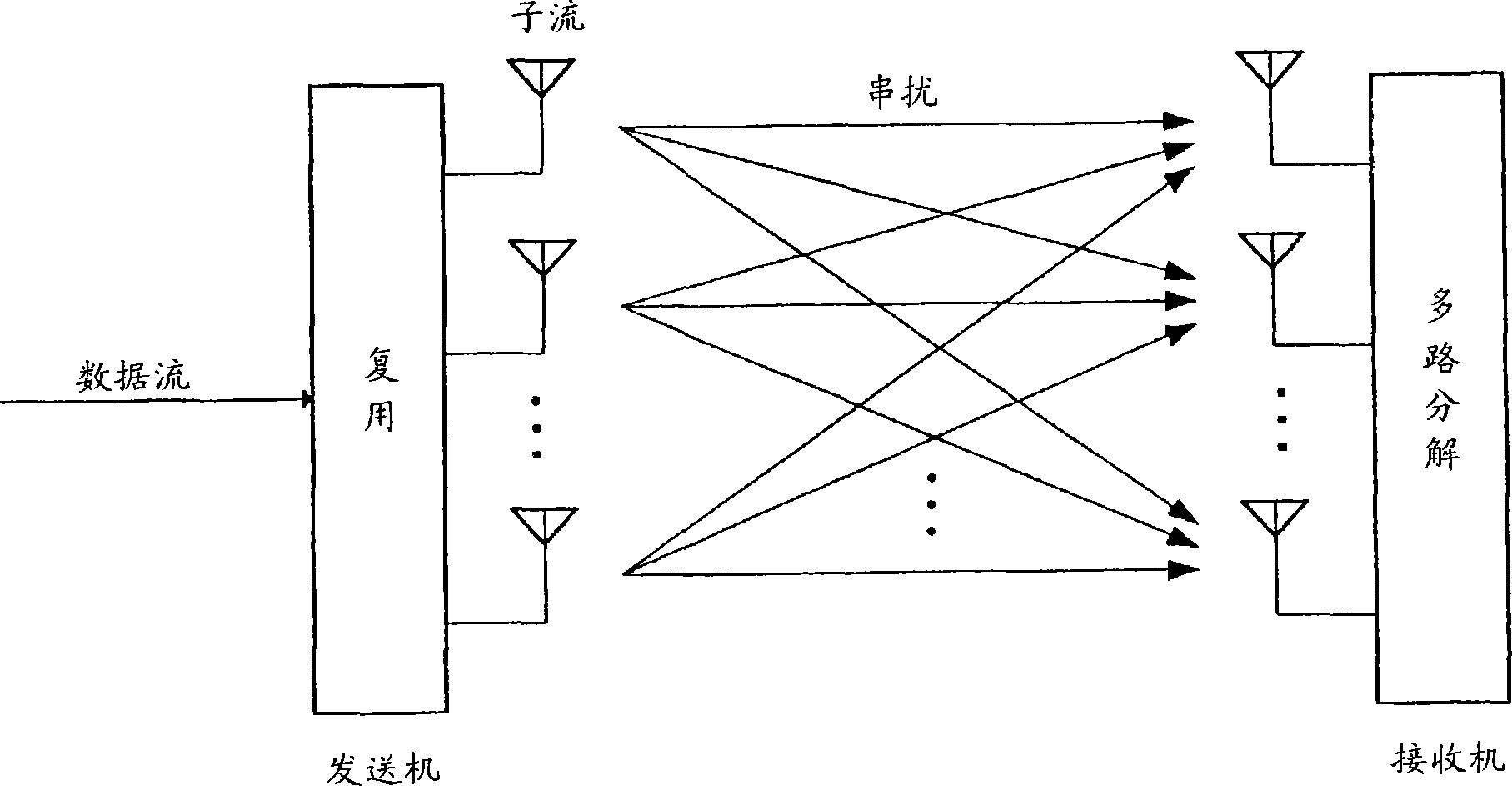
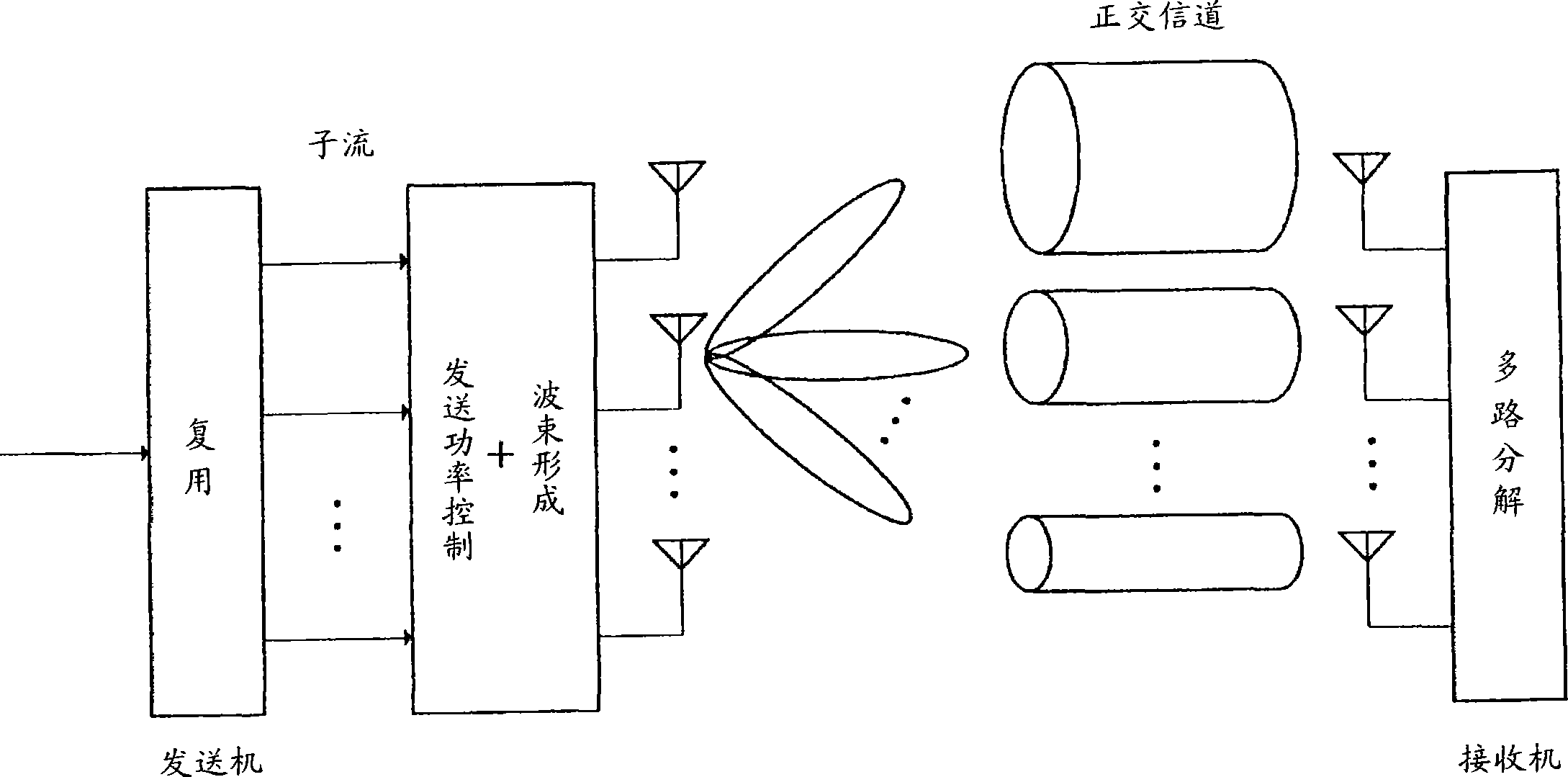
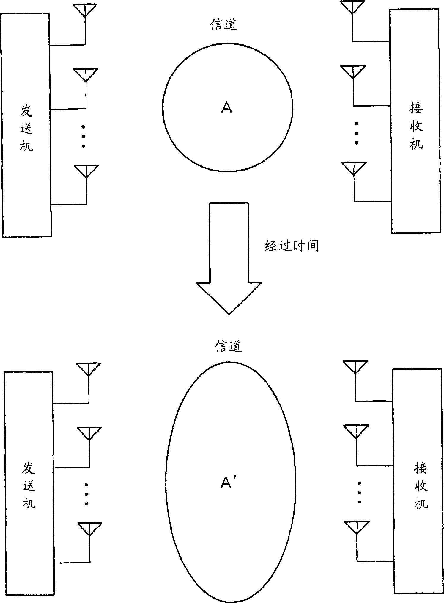
[0030] Figure 4 It is a block diagram showing the configuration of the transmitting and receiving device according to Embodiment 1 of the present invention. Figure 4 The structure of the transmitting and receiving device 100 mainly includes a modulation unit 101, a multiplexing unit 102, multiplication units 103-1 to 103-n, wireless transmission units 104-1 to 104-n, antennas 105-1 to 105-n, An antenna 106 , a wireless receiving unit 107 , a switching unit 108 and a storage unit 109 .

[0031] In addition, the structure of the transmitting and receiving unit 200 that communicates with the transmitting and receiving unit 100 mainly includes antennas 201-1 to 201-n, wireless receiving units 202-1 to 202-n, a multiplexing and demultiplexing unit 203, and a demodulation unit 204. , a channel estimation unit 205 , a channel change determination unit 206 , a storage unit 207 , a transmission weight generation unit 208 , a feedback information control unit 209 , a wireless transmi...

Embodiment approach 2

[0061] Figure 7 It is a block diagram showing the configuration of the transmitting and receiving device according to Embodiment 2 of the present invention. However, with Figure 4 The same part of the structure is appended with the Figure 4 For the same reference numerals, detailed descriptions thereof are omitted.

[0062] Figure 7 The sending and receiving device 300 and Figure 4 The difference of the transmitting and receiving device 200 is that the transmitting and receiving device 300 includes a wireless transmitting unit 301 and an antenna 302, and transmits a wireless signal including known symbols. Furthermore, Figure 7 The sending and receiving device 400 and Figure 4 The difference between the transmitting and receiving device 100 is that the transmitting and receiving device 400 includes an antenna 401, a wireless receiving device 402, a channel estimation unit 403, an antenna change determination unit 404, a storage unit 405, a transmission weight gene...

Embodiment approach 3

[0084] Figure 9 It is a block diagram showing the configuration of the transmitting and receiving device according to Embodiment 3 of the present invention. However, with Figure 4 The same part of the structure is appended with the Figure 4 For the same reference numerals, detailed descriptions thereof are omitted. Figure 9 The sending and receiving device 500 and Figure 4 The difference between the transmitting and receiving device 200 is that the transmitting and receiving device 500 includes a wireless transmitting unit 501 and an antenna 502, and transmits timing information at the start of transmission weight generation. Furthermore, Figure 9 The structure of the transmitting and receiving device 600 mainly includes an antenna 601 , a wireless receiving unit 602 , a timing unit 603 and a switching unit 604 .

[0085] exist Figure 9 In this example, the wireless transmission unit 501 transmits timing information as the start and end of transmission weight gene...


PUM


Abstract

Provided is a transmitting and receiving device that makes correct judgment on directionality-controlled spatial division multiplexing communication to improve transmission efficiency. In this device: the channel estimation unit (205) performs channel estimation using known symbols included in the received signal; the channel change determination unit (206) obtains the channel estimation result estimated in the previous process and the result of this time. The correlation value between the estimated channel estimation results is used to obtain the size of the channel change, so that it can be judged based on the size of the channel change whether to perform spatial division multiplexing communication with directional control or to perform spatial division multiplexing without directional control. communication. When the wireless receiving unit (107) receives the transmission weight, the switching unit (108) outputs the received transmission weight to the multiplication units (103-1 to 103-n). When the wireless receiving unit (107) receives a signal including an instruction to perform spatial division multiplexing communication without directivity control, the switching unit (108) outputs "1" indicating no directivity control as a transmission weight to the multiplier Unit (103-1 to 103-n).

Description

technical field [0001] The present invention relates to a sending and receiving device and a sending and receiving method, in particular to a sending and receiving device and a sending and receiving method suitable for space division multiplexing communication. Background technique [0002] As a method of enabling large-capacity communication without expanding the frequency band, there is a Multiple-Input Multiple-Output (MIMO: Multiple-Input Multiple-Output) technology that uses a plurality of transmitting and receiving antennas. Space Division Multiplexing (SDM: Space Division Multiplexing), as a multiple-input multiple-output (MIMO) technology, configures multiple antennas on the transmitter and receiver, and transmits different and independent signals from each antenna in the transmitter. Signal; in the receiver, according to the directivity of multiple antenna arrays, multiple different signals transmitted at the same time are spatially separated and received. Accordin...

Claims


Application Information

Patent Timeline
Patent Type & Authority Applications(China)
IPC IPC(8): H04J15/00H04J99/00H04B7/04H04B7/06H04B7/26H04L25/02
CPCH04B7/0628H04B7/0621H04L25/0202H04B7/0634H04B7/063H04B7/0615
Inventor 今井友裕
Owner OPTIS WIRELESS TECH LLC
Why Eureka
Try Eureka