Surface light source device

A surface light source, light source technology, applied in the direction of light source, point light source, slender light source, etc., can solve the problems of large light leakage, poor image aesthetics, reduced picture brightness, etc., to achieve high front brightness, improved contrast, Good directivity

Inactive Publication Date: 2007-02-21
ORMON CORP
View PDF5 Cites 23 Cited by
  • Summary
  • Abstract
  • Description
  • Claims
  • Application Information

AI Technical Summary

Problems solved by technology

In this way, the spread of the light emitted from the light exit surface 14 of the light guide plate 12 is large, and when there is a large amount of useless light, there are problems as follows: not only the light utilization efficiency of the surface light source device is reduced, but also the loss of light is large. prevents the improvement of frontal brightness
Since the leaked light overlaps with the image light passing through the liquid crystal panel 19

Method used


Image

  • Surface light source device
  • Surface light source device
  • Surface light source device

Examples


Embodiment 1

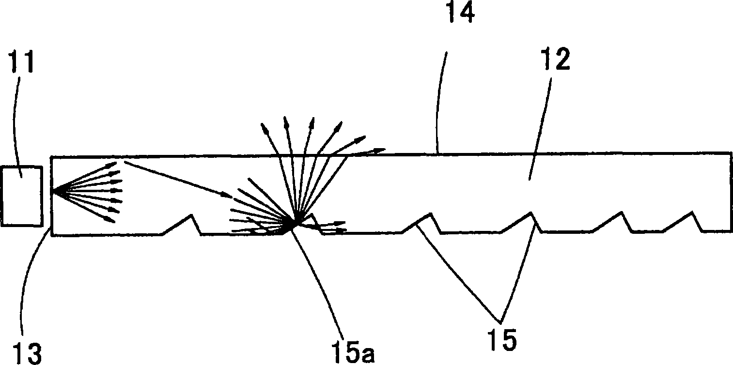
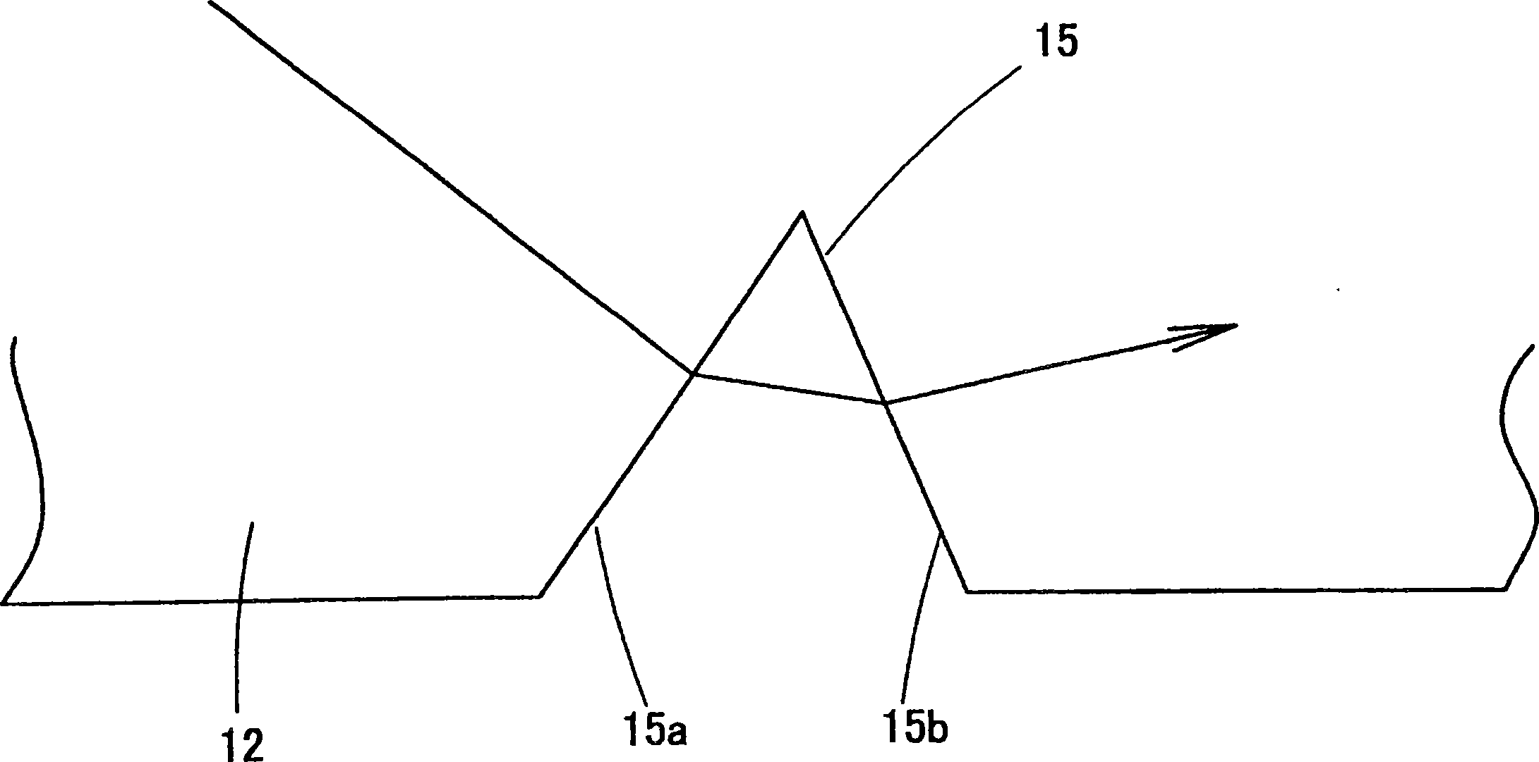
[0108] Figure 13 It is a perspective view showing a surface light source device according to an embodiment of the present invention. Figure 14 It is a schematic cross-sectional view of the surface light source device and a diagram showing the behavior of light in the light guide plate. Figure 15It is an enlarged cross-sectional view of the light guide plate showing the vicinity of the deflection pattern. This surface light source device is composed of a light source 21 and a light guide plate 22 . The light source 21 extends along the longitudinal direction of one side surface (light incident surface 23 ) of the light guide plate 22 to form a so-called linear light source. As such light source 21 , a cold cathode tube may be used, a linear light source may be formed by expanding the light representation of light emitting diodes (LEDs), or a linear light source may be formed by arranging a plurality of LEDs in a line. The light guide plate 22 is formed in a plate shape fr...

Embodiment 2

[0129] Figure 21 It is a perspective view showing a surface light source device according to another embodiment of the present invention. and, Figure 22 is a schematic cross-sectional view of the surface light source device. In this embodiment, between the light reflection portion 25 a and the flat portion 28 of the deflection pattern 25 , the directivity conversion portion 30 is constituted by an inclined surface (first inclined surface). Figure 23 It is an enlarged cross-sectional view showing the shape of the deflection pattern 25 and the directivity conversion part 30 . In this embodiment, the light reflection part 25a (second inclined surface) is also slightly extended to the lower surface side, and the directivity conversion part 30 is formed by providing an inclined surface between the flat part 28 and the extended light reflection part 25a. The inclined surface is formed so that it protrudes further to the lower surface side than the extension of the flat portion...

Embodiment 3

[0148] Figure 34 It is a cross-sectional view showing part of a surface light source device according to still another embodiment of the present invention. In this embodiment, the front end of the re-incident surface 25b protrudes outward from the extension of the flat portion 28, and a re-reflective surface 33 (fourth inclined surface) is formed on the side of the re-incident surface 25b away from the light source. The reflective surface 33 is for reflecting the light re-entered from the re-incident surface 25b toward the light-emitting portion 24 . Furthermore, the flat portion 28 is formed into a flat surface without any level difference by the rereflection surface 33 .

[0149] However, if Figure 34 As shown, according to this embodiment, the light leaked from the light reflection part 25a can be efficiently captured by the re-incident surface 25b, and then re-entered into the light guide plate 22, which can improve the utilization efficiency of light and reduce disturbi...


PUM


Abstract

The invention provides a sueface light device. A light source (21) is placed so as to face a light entry surface (23) of a light guiding plate (22). Light emitted from the light source (21) is guided in the light guiding plate (22). A recessed deflection pattern (25) is formed in the lower surface of the light guiding plate (22), and a directivity conversion section (30) is provided between a light reflection section (25a) and a flat section (28). The light reflection section is an inclined surface of the deflection pattern (25) and faces the light source side. The directivity conversion section (30) increases the directivity of light entering into the light reflection section (25a), increasing the directivity of light emitted from a light emission surface (24). The directivity conversion section (30) is constructed so as not to reflect light to the light reflection section (25a), the light being, for example, light obliquely emitted at a large angle relative to the normal to the light emission surface (24) after reflected at the light reflection surface (25a).

Description

technical field [0001] The invention relates to a surface light source device. In particular, it relates to a surface light source device such as a backlight and a front light for illuminating an image display panel such as a liquid crystal panel. Background technique [0002] A surface light source device composed of a light source and a light guide plate is used as the backlight and front light for illuminating the liquid crystal panel. In such a surface light source device, the following characteristics are required: (1) the light from the light source can be efficiently emitted from the light guide plate to the liquid crystal panel, and (2) the light from the light source can be uniformly emitted from the light guide plate in a planar manner. [0003] As a surface light source device having the above-mentioned characteristics, there are surface light source devices in which concave-convex patterns are provided on the surface of the light guide plate facing the light exi...

Claims


Application Information

Patent Timeline
IPC IPC(8): F21V8/00G02F1/13357F21Y101/02F21Y103/00F21Y115/10G02F1/1335
Inventor 松井优贵船本昭宏青山茂广田和英篠原正幸
Owner ORMON CORP
Why Eureka
Try Eureka