Gas generator

A generator and gas technology, applied in the manufacture of combustible gas, petroleum industry, combined combustion mitigation, etc., can solve the problems of increasing the cost of gas production, gas escape, distribution, etc., so as to improve the efficiency and effect of gas production and improve production. Speed, cost-effective results

Inactive Publication Date: 2007-02-28
常熟市伟成非织造成套设备有限公司
View PDF1 Cites 2 Cited by
  • Summary
  • Abstract
  • Description
  • Claims
  • Application Information

AI Technical Summary

Problems solved by technology

Although there is no shortage of gas generators in the literature, none of them can be used for the above-mentioned equipment.
As we all know, in the process of gas generator gas production, coal must be frequently added to the furnace, and every time coal is added, the coal inlet door must be opened once, and when the coal inlet door is opened to add coal, the coal generated in A large amount of gas in the furnace will escape to the outside. On the one hand, it will cause low gas production efficiency and effect, and increase the cost of gas production. On the other hand, there will be safety hazards due to gas escape.
[0003] Though the disclosed a kind of gas generator of Chinese Patent Auth

Method used


Image

  • Gas generator
  • Gas generator
  • Gas generator

Examples


Embodiment 1

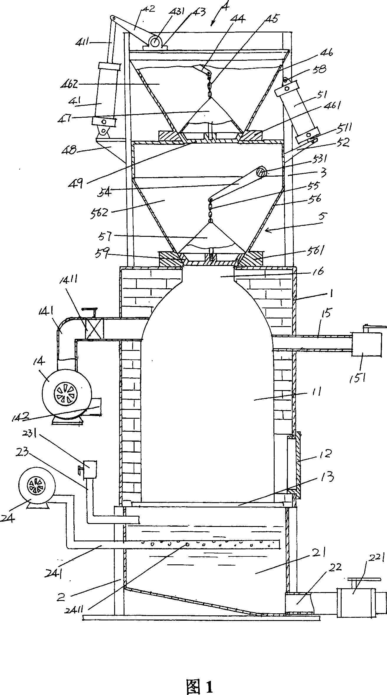
[0021] Referring to FIG. 1 , refractory bricks or other similar materials can be used as a heat insulation layer between the furnace 11 and the furnace body 1 . The upper portion of the furnace body 1 is respectively connected with a gas outlet pipe 15 and a smoke exhauster 14 communicated with the furnace 11 , and a control valve is arranged on the pipeline of the gas outlet pipe 15 . The water gas generated in the furnace 11 is led to corresponding devices by the gas outlet pipe 15 for use, for example, to the ovens of production devices such as the aforementioned spray-bonded cotton, hard cotton, non-glued cotton, and tenter setting machines. Combustion for heating. And the smoke exhaust machine 14 is only used when igniting the coal seam on the grate 13, because it needs to be ignited by means of materials such as firewood that are heterogeneous with coal when igniting the initial stage, so smoke can be produced, by opening the smoke exhaust pipe The valve 1411 is led out...

Embodiment 2

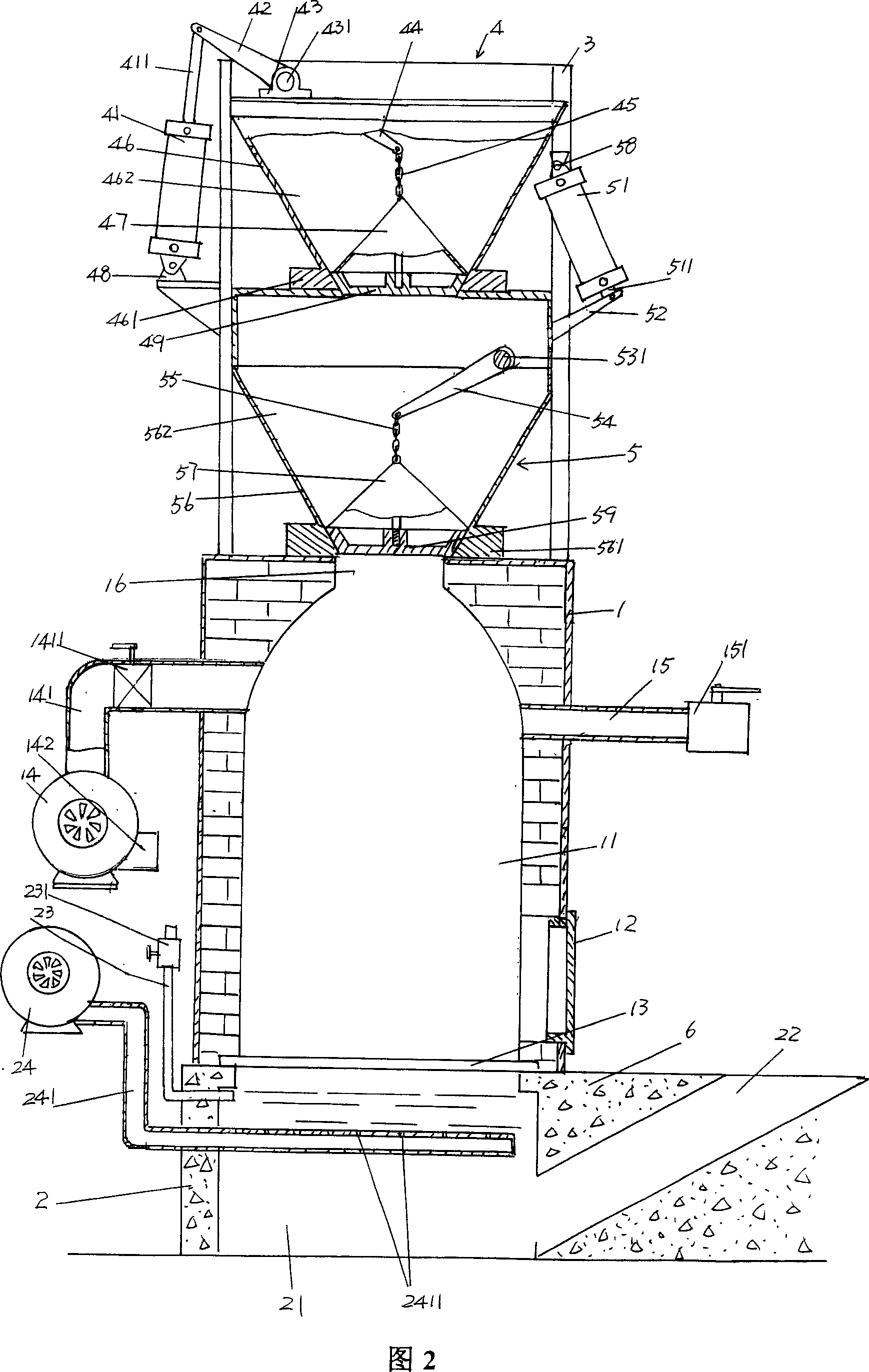
[0024] Please refer to Fig. 2, the sealing body 2 provided in this embodiment is a structural form cast by concrete 6, and the ash discharge port 22 is arranged obliquely, and the ash discharge port 22 can reflect the function of ash discharge while the furnace 11 is working. The effect, therefore, is superior to that shown by the ash outlet 22 in FIG. 1 . All the other are the same as the description of embodiment 1.

Embodiment 3

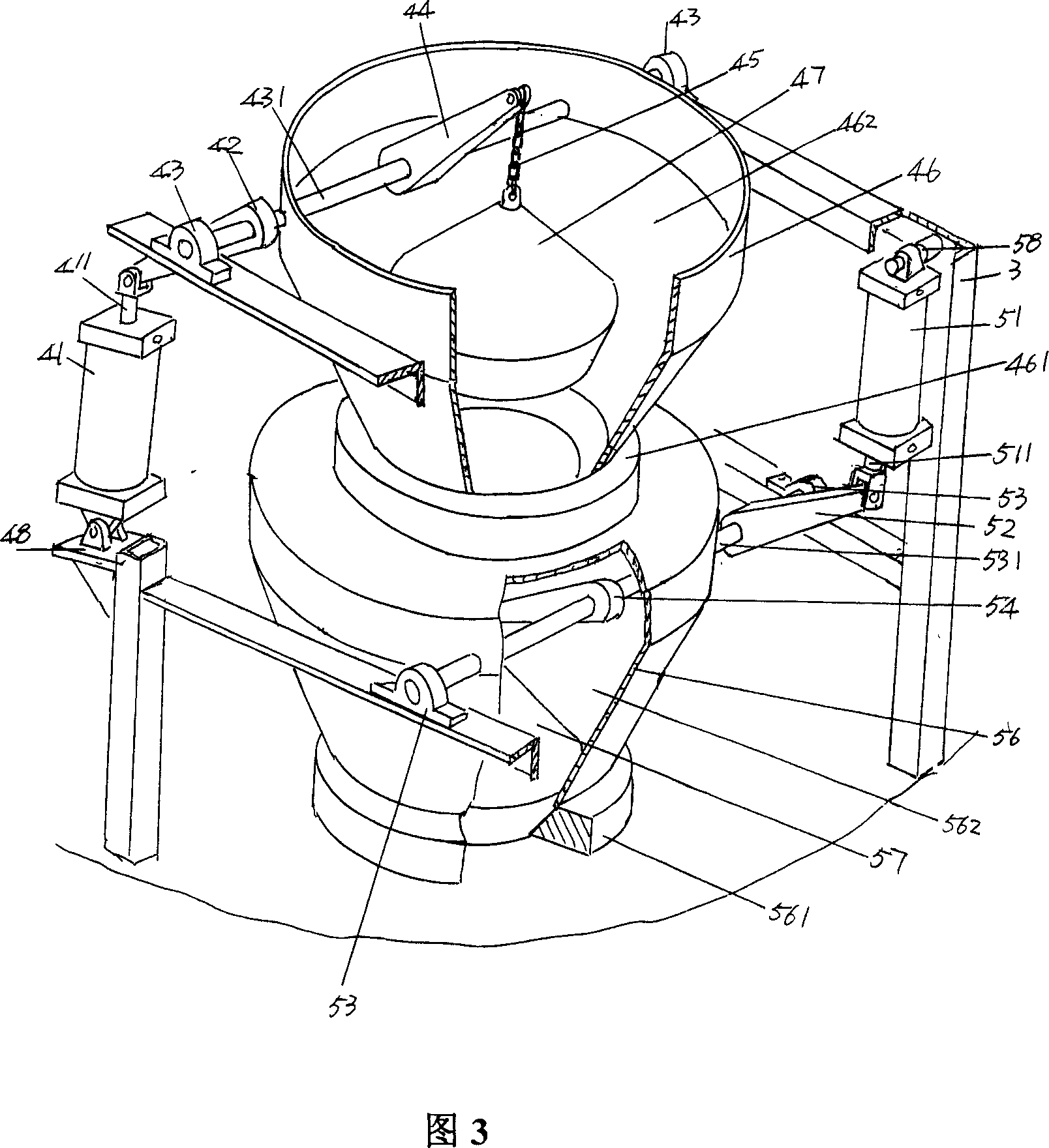
[0026] Please refer to Fig. 3 and in conjunction with Fig. 1, as the first bucket body 56 of the lower coal guiding mechanism 5 of the present invention, it is sealed and fixed on the top of the furnace body 1 through the lower cover plate 561 extending at the bottom of the coal drawing mechanism 5 of the present invention. Cavity 562 communicates with the coal inlet 16 on furnace 11 top or is closed by first cone block cover 57 to take on. The bottom of the first cone retaining cover 57 is fixedly connected with the lower cover 59 by bolts, and the lower cover 59 is formed with a conical surface, which just matches with the inner conical surface of the upper cover plate 561, so as to reflect the impact of coal-feeding. Excellent sealing effect of port 16.

[0027]Seen from Fig. 3, the first cylinder 51 is arranged on the grate 3 by the first cylinder block 58, the cylinder column 511 of the first cylinder block 58 is hinged with one end of the crank arm 52 of the first cylind...


PUM


Abstract

The invention relates the gas generator, belonging to gas generator device field. The device has a furnace body and sealed body. On the furnace there are gas draw-off tube and smoke discharging machine, at the side of the furnace there is door, at the bottom of the furnace there is a grate which becomes inlet at the top of furnace; on the sealed body there is air inducing device and supplying water tube, at the bottom of the sealed body there is ash draw-off tube, on the furnace there is furnace frame, on the bottom of furnace frame there is lower leading coal device, on the top of the furnace frame there is a upper leading coal device. The device can improve gas production efficiency and avoid hidden danger; the air inducing device can improve production rate; the device can provide energy source and save cost.

Description

technical field [0001] The invention relates to a gas generator, which is used to provide energy for production devices such as glued cotton, hard cotton, non-glued cotton, tenter setting machine and the like, and belongs to the technical field of gas generators. Background technique [0002] At present, the energy used to provide heat sources for production equipment such as glued cotton, hard cotton, non-glued cotton, and stenter setting machines is diesel oil, which is sucked into the oven by a fan through a burner. Taking a 12m x 3m oven for the production of glued cotton as an example, the diesel consumption per hour is 40-52Kg, and the diesel consumption for 24 hours a day is 960-1248Kg, that is, about one ton of diesel is consumed per day. The required cost is about 4500-5800 yuan (current price). Therefore, on the one hand, it consumes a large amount of resources unreasonably, and on the other hand, it leads to an ineffective increase in the production cost of the e...

Claims


Application Information

Patent Timeline
IPC IPC(8): C10J3/20
CPCY02E20/18
Inventor 王浦国王卫成
Owner 常熟市伟成非织造成套设备有限公司
Why Eureka
Try Eureka