
Depth measurement drainage plate structure provided with shielding layer

A shielding layer and drainage board technology, applied in soil protection, infrastructure engineering, construction, etc., can solve problems such as difficulty in grasping the actual depth of drainage components, achieve broad industrial application and promotion prospects, ensure measurement accuracy, and be easy to use Effect

Inactive Publication Date: 2007-02-28
浙江宾王工程材料有限公司
View PDF1 Cites 1 Cited by
  • Summary
  • Abstract
  • Description
  • Claims
  • Application Information

AI Technical Summary

Problems solved by technology

[0004] However, in actual use, after the depth-measuring drainage component is inserted into the ground, the sounding line will be affected by the geomagnetic field, so that a potential difference will be generated between the two wires (when the depth-measuring drainage component is not inserted underground, there will be no This potential difference), this potential difference will affect the accuracy of the measurement results of the capacitance value alone, or will affect the accuracy of the measurement results of the capacitance value after being superimposed with the measurement voltage applied between the two strands of wires, which makes it difficult to grasp the insertion of the drainage component into the ground. actual depth

Method used


Image

  • Depth measurement drainage plate structure provided with shielding layer
  • Depth measurement drainage plate structure provided with shielding layer
  • Depth measurement drainage plate structure provided with shielding layer

Examples


Embodiment 1

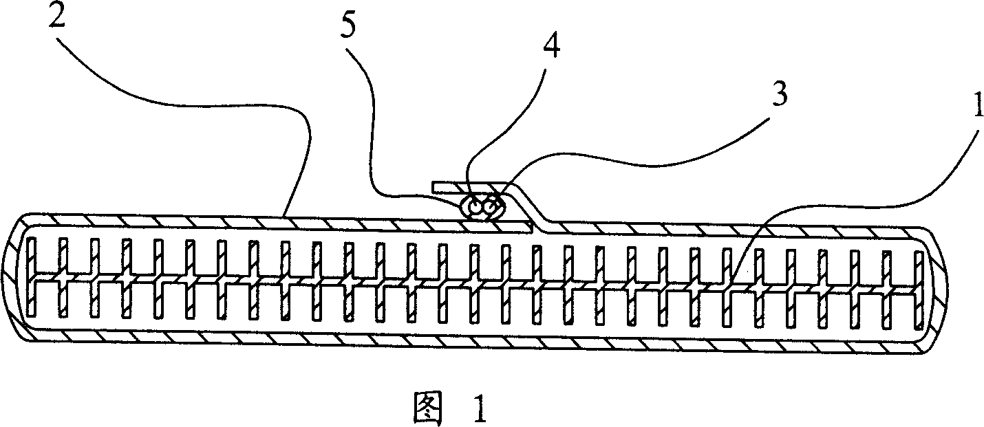
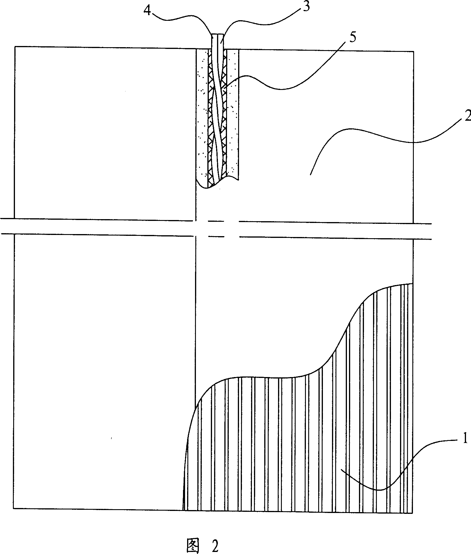
[0021] As shown in Figures 1 and 2, the depth-measuring drainage plate member with shielding layer, the core plate 1 is made of plastic plate or synthetic resin net, and several longitudinal drainage channels are opened on both sides of the core plate, and the filter membrane layer 2 is wrapped outside the core plate. The filter membrane layer 2 can be made of non-woven fabric or bonded with chemical glue. In the seam of the filter membrane layer 2, two enameled wires (depth-sounding wires) 3, 4, which are regularly intertwined, are longitudinally placed. The enameled wire is evenly wound on the longitudinal axis. The two enameled wires 3 and 4 are covered with a layer of aluminum-plastic composite tape 5, which constitutes a magnetic field shielding layer.

Embodiment 2

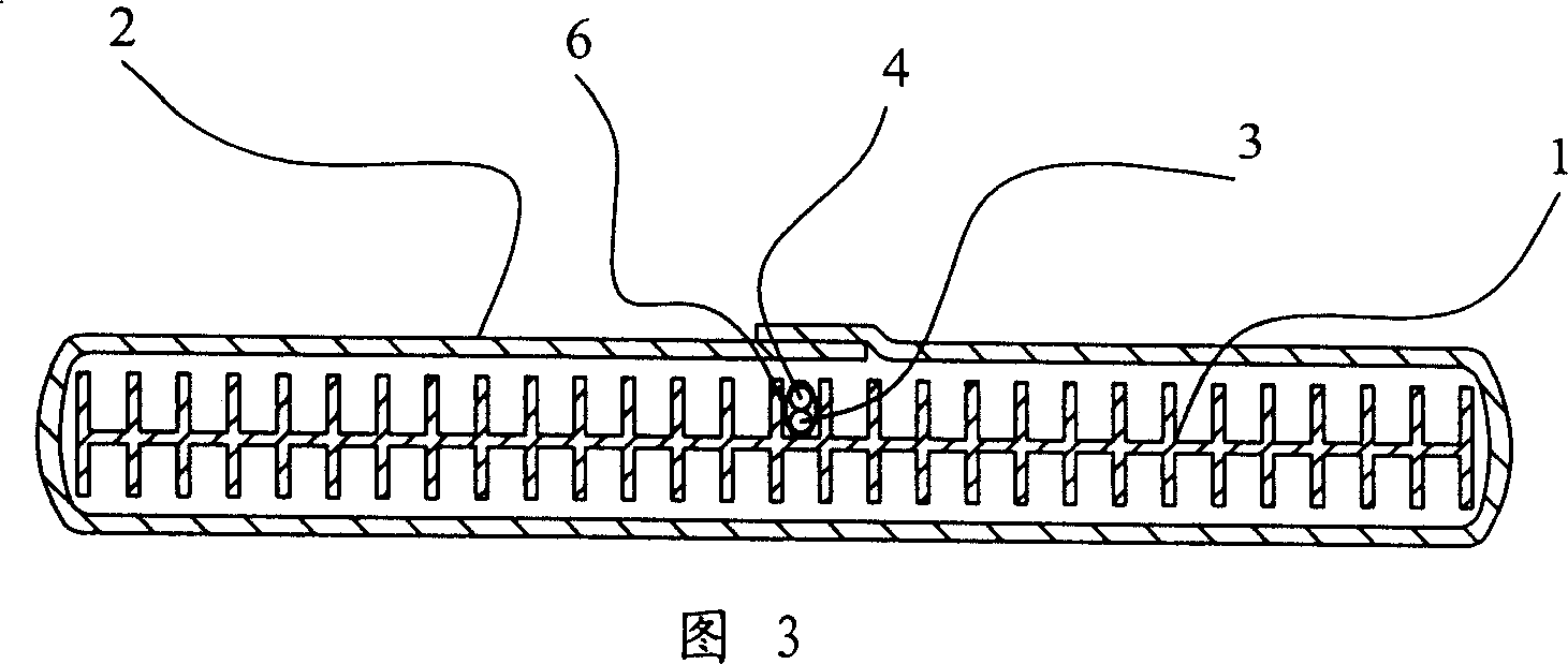
[0023] As shown in Figure 3, the depth-measuring drainage plate component with a shielding layer, the two enameled wires 3, 4 are regularly intertwined, and the enameled wire is coated with a layer of shielding paint 6 and placed on the core plate 1 corresponding to the bonding place of the filter membrane layer. In the drainage channel, other structures are the same as those in Embodiment 1.

Embodiment 3

[0025] As shown in Figures 4 and 5, the depth-measuring drainage plate member with a shielding layer, the shielding sleeve 7 is covered outside the two parallel parallel metal wires 3, 4, and the isolation sleeve 7 is arranged outside the filter membrane layer 2 (not limited to Fig. The bonding place shown can be any suitable position on the outer surface of the filter membrane layer), and other structures are the same as in Embodiment 1.

[0026] The mutual setting method and setting position of the two strands of sounding lines involved in the present invention, and the structure of the shielding layer can be freely combined according to the actual situation according to the schematic diagram of the above-mentioned embodiments (for example, the spacer sleeve covering the parallel parallel metal wires is arranged on the The bonding place of the non-woven filter membrane layer) to achieve the use effect according to local conditions.

[0027] When in use, after the drainage me...


PUM


Abstract

The invention relates to a discharge element with shield layer, which can detect the depth, wherein said discharge element is used to discharge water at soft foundation with high water content, to detect its depth under ground. Said invention comprises: a core plate with longitudinal discharge channel and the filter film layer packing the core plate; and the invention is characterized in that: it has longitudinal depth-detecting element, which comprises at least two depth-detecting lines whose relative positions are fixed and insulated; said depth-detecting element is packed with magnetic field shield layer, with simple operation and high accuracy.

Description

【Technical field】 [0001] The invention relates to a depth-measuring drainage component provided with a shielding layer. The drainage component is used for drainage of soft soil foundations with high water content, and is convenient for detecting the depth inserted into the ground by instruments. 【Background technique】 [0002] Existing drainage components generally include a core plate made of plastic or synthetic resin mesh and a filter membrane layer wrapped outside the core plate (usually bonded or sewn with non-woven fabrics), and the core plate has longitudinal drainage on both sides. aisle. When dealing with soft soil foundations with high water content, the drainage components are inserted into the ground, and then pressure is applied to the foundation to make the groundwater flow to the surface through the drainage channel to be discharged. In order to facilitate the measurement of the depth of the drainage board inserted into the ground, effectively control the con...

Claims


Application Information

Patent Timeline
Patent Type & Authority Applications(China)
IPC IPC(8): E02D3/10
Inventor 任再永
Owner 浙江宾王工程材料有限公司
Learn More