
Multifunctional girder structure experimental bench

A technology of a truss structure and an experimental bench, applied in teaching models, instruments, educational appliances, etc., can solve the problems of not being able to give full play to students' imagination and creativity, and achieve the effects of improving hands-on ability, convenient disassembly and assembly, and low cost

Inactive Publication Date: 2007-02-28
SHANDONG UNIV
View PDF0 Cites 10 Cited by
  • Summary
  • Abstract
  • Description
  • Claims
  • Application Information

AI Technical Summary

Problems solved by technology

During the experiment, the students only repeat the main steps according to the experiment instruction book, which cannot give full play to the imagination of the students and stimulate the creativity of the students

Method used


Image

  • Multifunctional girder structure experimental bench
  • Multifunctional girder structure experimental bench
  • Multifunctional girder structure experimental bench

Examples


Embodiment 1

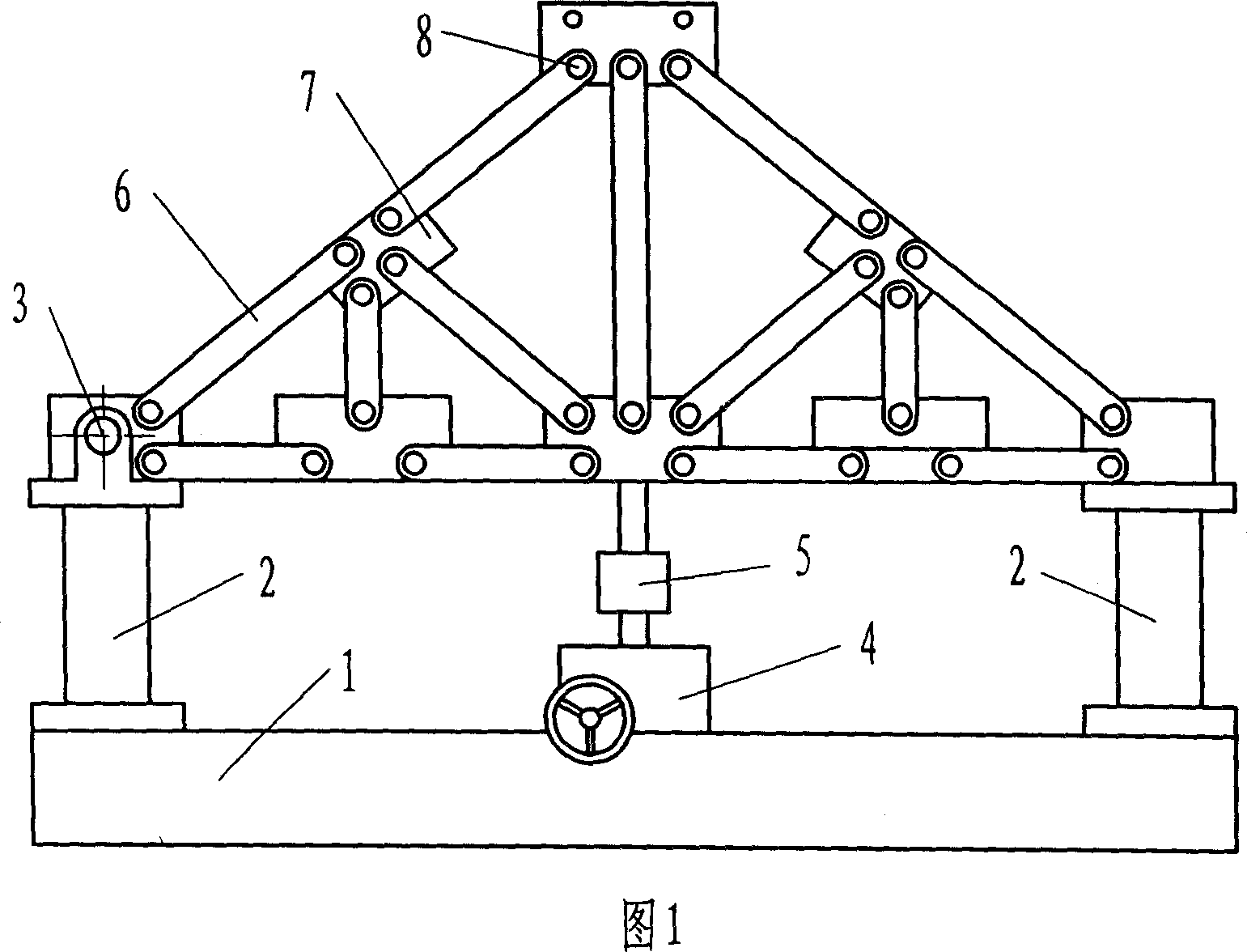
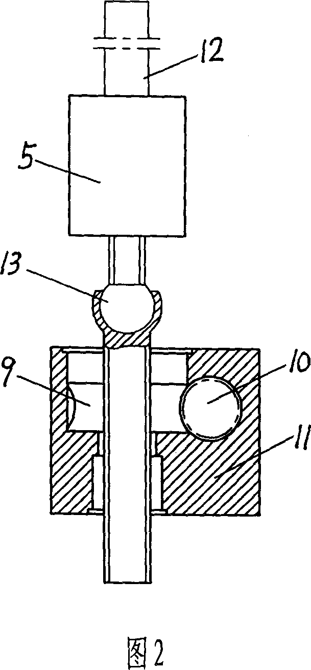
[0021] As shown in Figure 1, the truss of this embodiment is a lower cable-stayed frame model, including a base 1, a column 2, a connecting rod 6, a connecting piece 7, a pin 8, a loading device 4 and a load sensor 5, and the two ends of the base 1 are respectively Connected with columns 2, a total of thirteen connecting rods 6 are connected together through eight connecting pieces 7 and twenty-six pins 8 to form a lower cable-stayed model frame, and the two ends of the model frame are respectively connected to the upper ends of the columns 2 at both ends of the base , one end of which is hinged with the column 2 through the pin shaft 3, and the other end can be installed with a pulley below to form a free sliding connection, which can move under load to adapt to its displacement. The loading device 4 is installed on the base 1 and can move on the base 1 so as to exert force on the connecting rods at different positions.

[0022] The structure of loading device 4 is shown in F...

Embodiment 2

[0027] As shown in Figure 6, the truss of this embodiment is an inverted W frame model, which is formed by connecting thirteen connecting rods through eight connecting pieces and twenty-six pins. All the other structures are the same as in Example 1.

[0028]

Embodiment 3

[0030] As shown in FIG. 9 , the truss of this embodiment is a rhombus frame model, which is formed by connecting seventeen connecting rods through ten connecting pieces and thirty-four pins. All the other structures are the same as in Example 1.

[0031]

[0032] It can be seen from the data in the tables of the above three embodiments that the multifunctional truss structure test bench of the present invention has good test accuracy.


PUM


Abstract

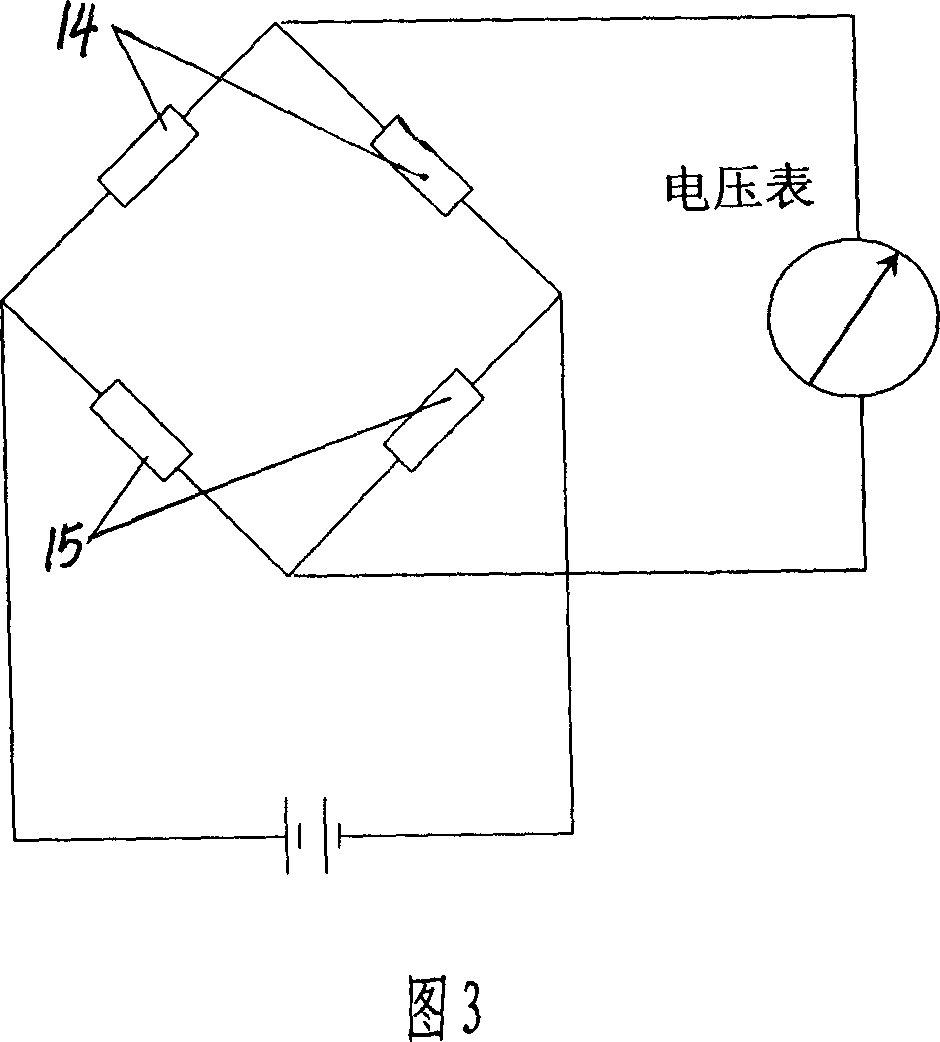
The invention relates to a multifunctional truss structure test bench, which comprises base, column, model support and loader, wherein two ends of base are connected to columns; the model support are formed by one group of connecting rods connected by connecting plates and pins; two ends of model support are connected to the upper ends of columns at two ends of base, while one end has hinge connection and another end has free sliding connection; the loader is mounted on the base to move on it, while its transmission axle is connected to the model support; the loader is mounted with load sensor whose output via signal collector is connected to the computer. The invention can form variable models via different demands, to analyze stress of model via electric test, with low cost.

Description

technical field [0001] The invention relates to a teaching experiment instrument of a truss structure, in particular to a truss structure experiment platform with the purposes of teaching, bridge design, house design, construction demonstration and the like. Background technique [0002] In recent years, due to the unique advantages of truss structures and the increasingly mature research on intersecting joints, various giant lattice members are more and more widely used in long-span roofs and bridges. Space truss beams are composed of multiple plane trusses. Such space lattice members not only have vertical stiffness, but also have large out-of-plane stiffness. At the same time, they have the characteristics of plane systems. During the structural layout, a space truss beam can be arranged on each axis, and the force transmission of secondary components (such as secondary trusses and purlins) and the force relationship of the space truss beam can also be decomposed during s...

Claims


Application Information

Patent Timeline
IPC IPC(8): G09B25/00
Inventor 汤红卫曲英姿马惠敏汪保良
Owner SHANDONG UNIV
Learn More