Aging testing apparatus and method

A test board and temperature sensor technology, which is applied in the direction of measuring electricity, measuring devices, measuring heat, etc., can solve the problems of temperature sensor damage, integrated circuit damage, etc.

Inactive Publication Date: 2007-02-28
WELLS CTI LLC
View PDF2 Cites 21 Cited by
  • Summary
  • Abstract
  • Description
  • Claims
  • Application Information

AI Technical Summary

Problems solved by technology

Direct contact between temperature sensors can cause damage to the integrated circuit due to point loading of the relatively small temperature sensor on the integrated circuit when the socket is clamped closed
Damage to the temperature sensor can also result from direct contact of the integrated circuit to the sensor

Method used


Image

  • Aging testing apparatus and method
  • Aging testing apparatus and method
  • Aging testing apparatus and method

Examples


Embodiment Construction

[0030] A. IC package temperature control device and method

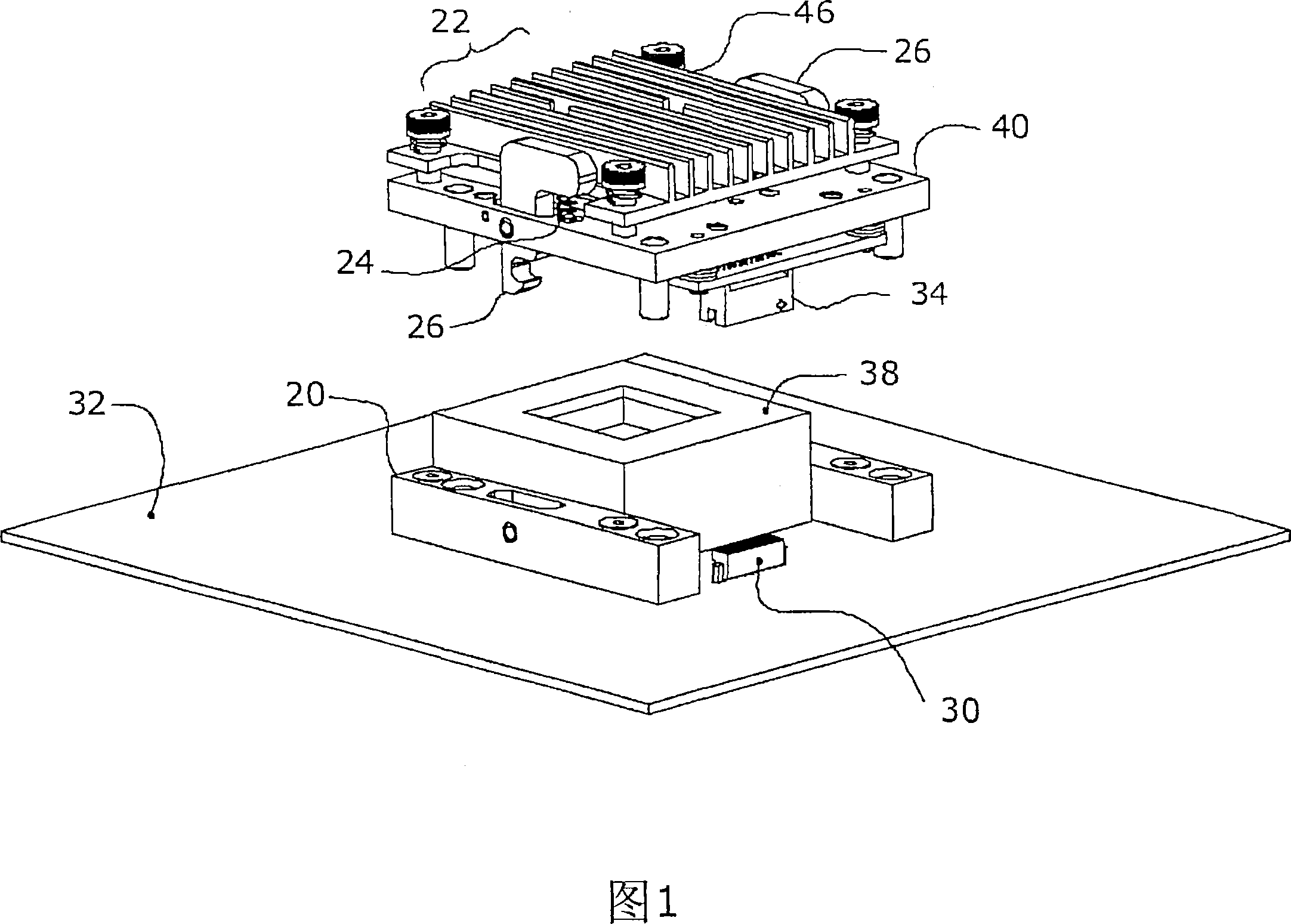
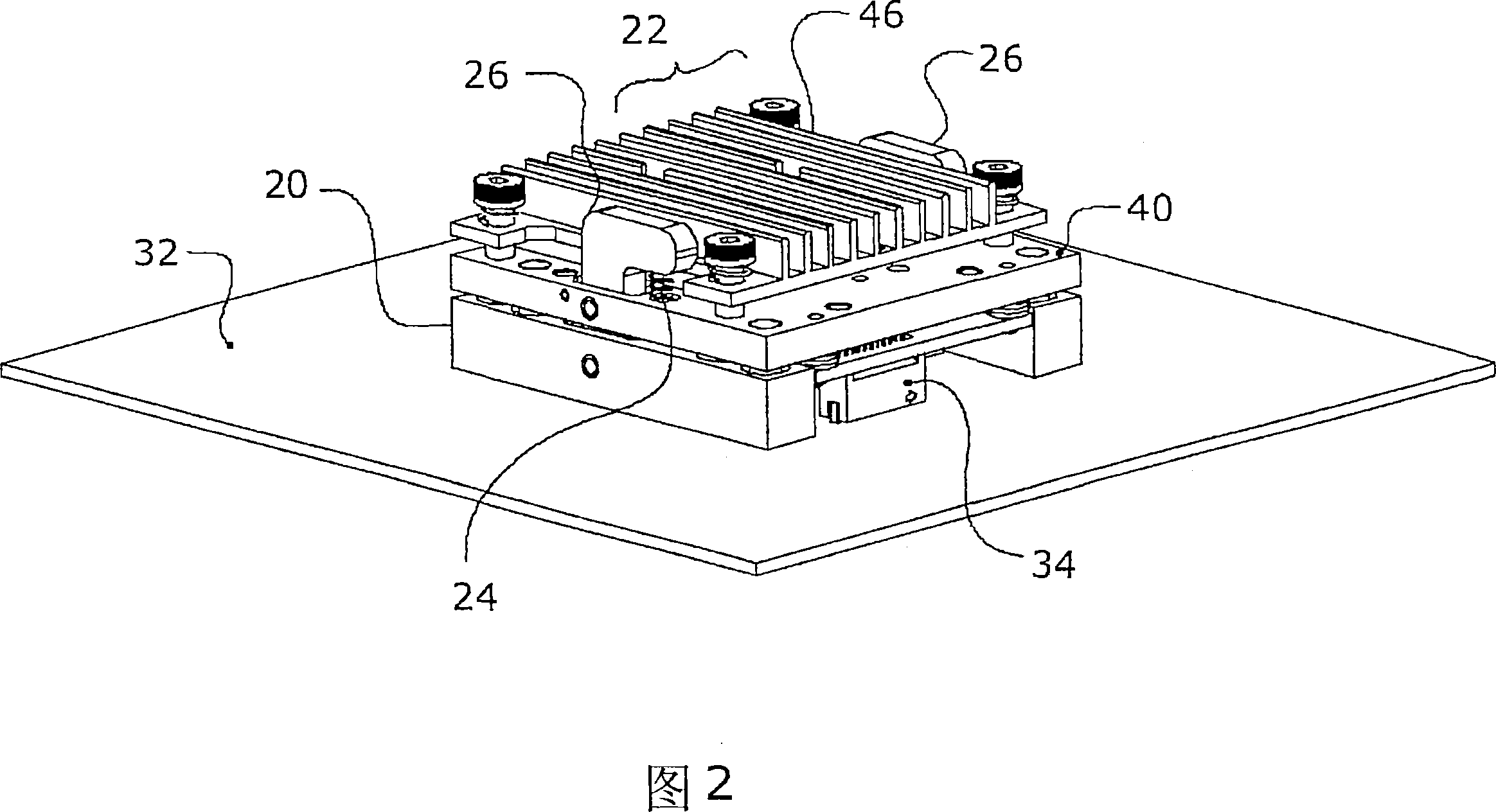
[0031] 1 and 2 show perspective views of a test socket 20 and a module sensor / heater / controller unit 22 according to one embodiment of the present invention. The heater may also be a cooler, but is hereinafter referred to simply as a heater for brevity. The spring 24 on the latch 26 allows easy and quick release of the heater unit 22 from the test socket base 38 . FIG. 2 shows the test socket 20 and the modular unit 22 in the closed position, with the board-side connector 30 on the test board 32 receiving the communication / power connector 34 on the heater unit 22 .

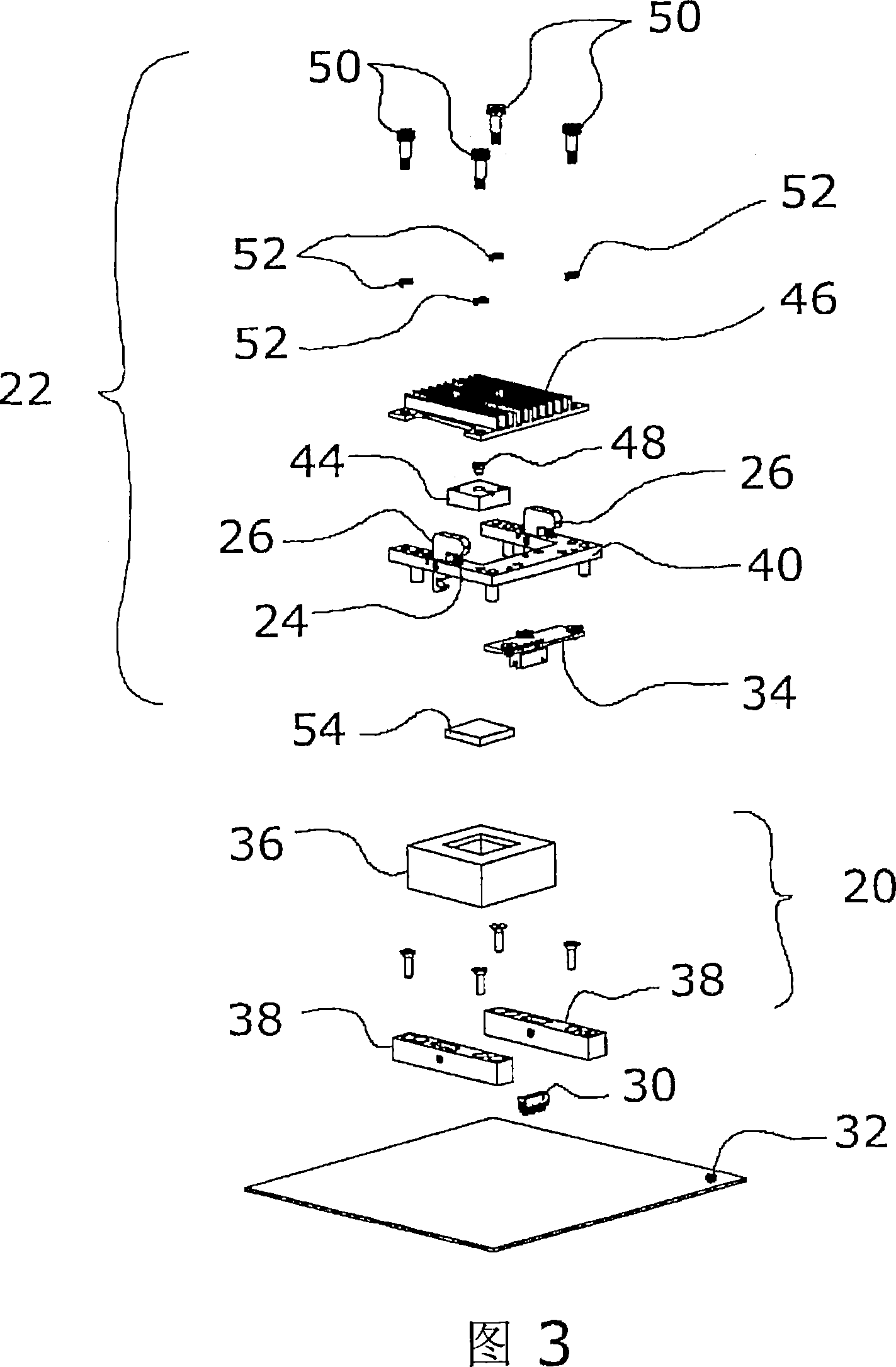
[0032] FIG. 3 shows an exploded perspective view of the test socket 20 , the modular unit 22 and the test board 32 . The test socket 20 utilizes a general open top socket 36 fastened to a base 38 with an alignment pin 41 and two latches 26 . The modular unit 22 has a guide plate 40 for aligning the modular unit 22 onto the base 38 and the board-side c...


PUM


Abstract

An integrated circuit (IC) package testing apparatus integrates a temperature sensor (48), heater (or cooler) (44), and controller (42) within a single modular unit (22, 72). The controller (42) is a microprocessor embedded within the modular unit (22, 72) and in communication with the sensor (48) and heater (44). The controller (42) allows a selected testing temperature to be input by a user via a communications link (71) to the controller (42). Each IC package (54) has its testing temperature individually controlled by a controller (42). The module is easily attached and removed from an open-top socket through the use of latches on the testing socket.

Description

technical field [0001] The present invention relates to integrated circuit testing sockets, and more particularly to integrated circuit testing and / or temperature control of integrated circuits in burn-in sockets. Background technique [0002] Integrated circuit (IC) packages must be tested after their manufacture, usually at elevated temperatures, which is typically a burn-in process. During this process, it is often necessary to control the temperature of ICs, sensors and other components. Techniques for doing so have been widely practiced over the years. This system typically consists of a heater (or cooler), a temperature sensor, and a comparator that applies power to the heater in proportion to the difference in voltage measured at the temperature sensor compared to a reference voltage. This energy is applied in the proper direction to cause the differential voltage to decrease. For these purposes, many types of temperature sensors and temperature control modules are...

Claims


Application Information

Patent Timeline
Patent Type & Authority Applications(China)
IPC IPC(8): G01R31/02G01K1/02
Inventor 克里斯托弗·A·洛佩斯布赖恩·J·登海尔戈尔·B·金斯特
Owner WELLS CTI LLC
Why Eureka
Try Eureka