
Liquid ejection apparatus

一种喷射装置、液体喷射头的技术,应用在印刷等方向,能够解决墨水雾化、喷嘴堵塞、印字不良等问题

Inactive Publication Date: 2007-03-07
SEIKO EPSON CORP
View PDF1 Cites 5 Cited by
  • Summary
  • Abstract
  • Description
  • Claims
  • Application Information

AI Technical Summary

Problems solved by technology

[0003] In such printers, there is a problem that the nozzles are clogged due to the increase in ink viscosity or solidification due to the evaporation of the ink solvent from the nozzles of the recording head, the adhesion of dust, and the incorporation of air bubbles, resulting in poor printing.
However, if the nozzle formation surface of the recording head is too close to the recording medium side in order to narrow the distance between the recording head and the recording medium, the preliminary ejection cover that moves during ejection will come into sliding contact with the nozzle formation surface, which may cause Printing is bad, or the preliminary ejection cover may become a resistance when moving
In addition, if the distance between the recording head and the recording medium is widened (for example, 3mm or more) in order to avoid such sliding resistance, the ink ejected from the recording head will bleed when attached to the recording medium through the opening of the preliminary ejection cover. may cause poor printing or fogging of ink that is not ejected onto the recording medium

Method used


Image

  • Liquid ejection apparatus
  • Liquid ejection apparatus
  • Liquid ejection apparatus

Examples


Embodiment Construction

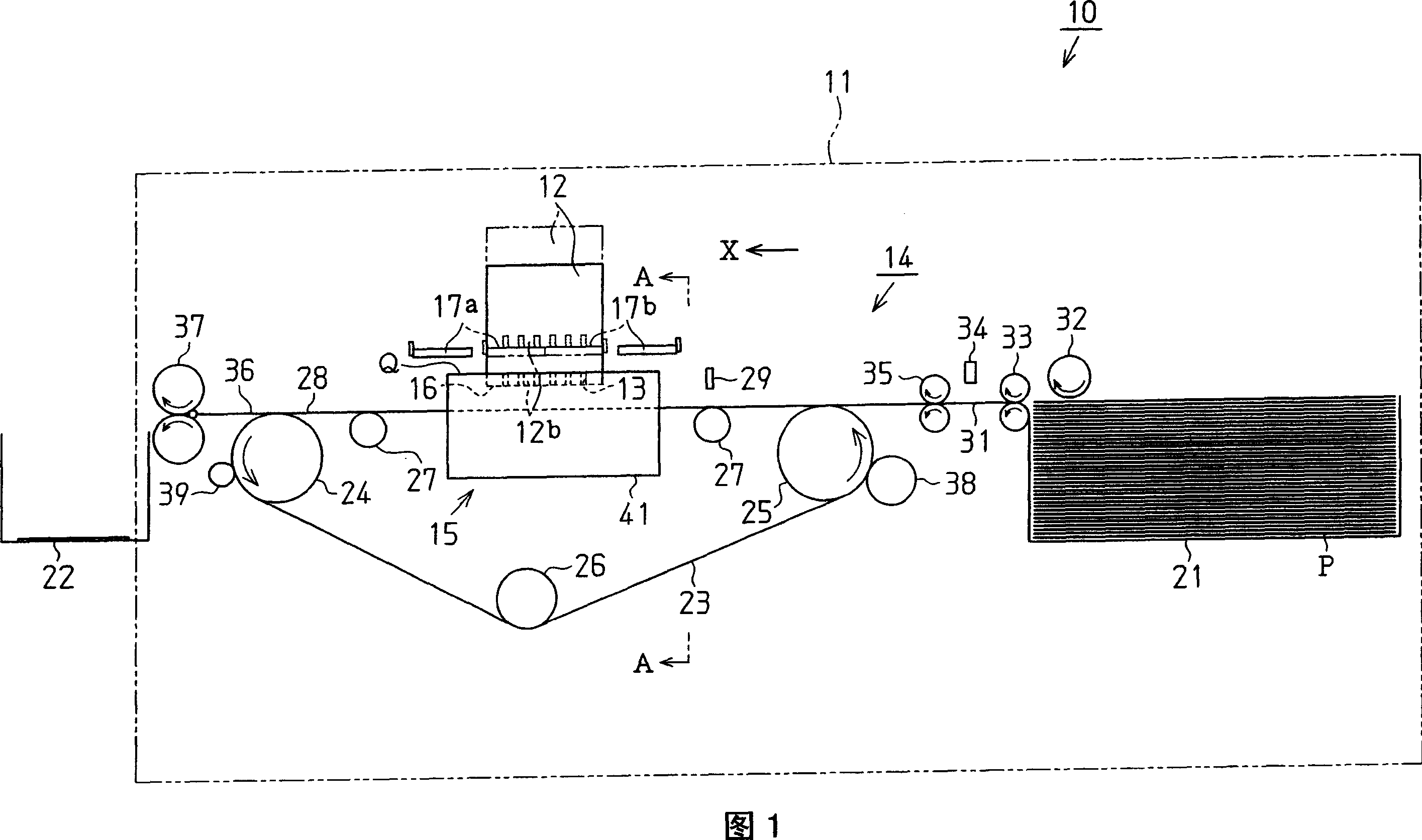
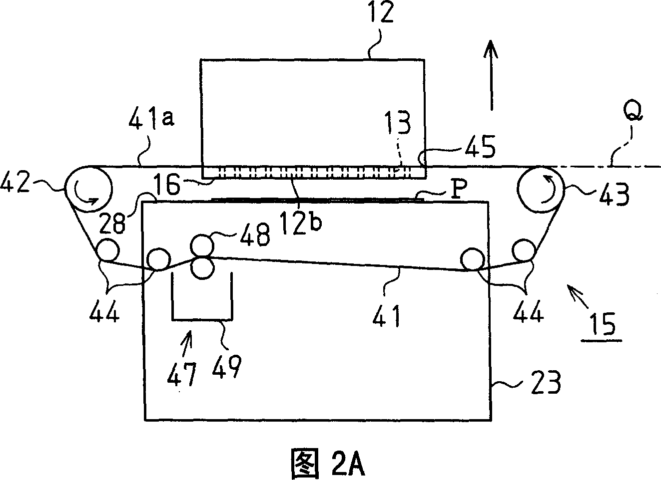
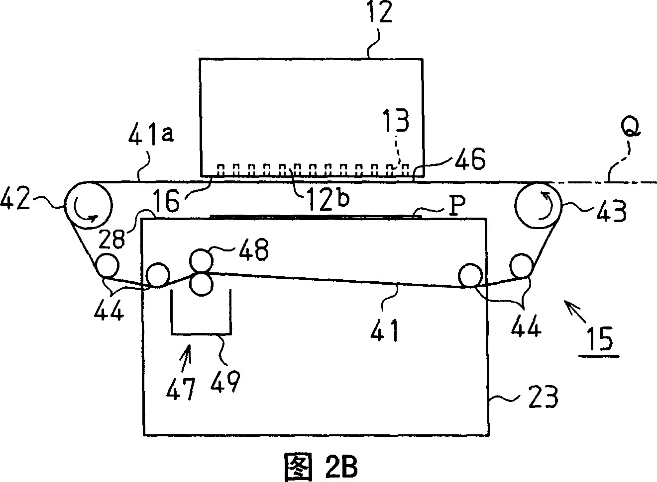
[0014] An embodiment of the present invention will be described below with reference to FIGS. 1 to 4 .

[0015] As shown in FIG. 1 , an inkjet printer (hereinafter referred to as “printer”) 10 as a liquid ejecting device according to the present embodiment includes a substantially box-shaped main body casing 11 . A recording head 12 (liquid ejection head) for ejecting ink (liquid) onto a target paper P is disposed substantially in the center of the main body casing 11 .

[0016] On the nozzle forming surface 16, which is the lower surface of the recording head 12, a plurality of nozzles 13 are formed over the entire width of the printing area of ​​the paper P in a direction intersecting the conveying direction of the paper P (direction X indicated by an arrow in FIG. 1 ). , the recording head 12 does not reciprocate in a direction intersecting the transport direction of the paper P during printing. In this regard, the printer 10 of the present embodiment is not a type in whic...


PUM


Abstract

A liquid ejecting device comprising: a liquid ejecting head having a nozzle forming surface on which a liquid ejecting nozzle is provided; a part of a liquid receiving member having an opening larger than the nozzle forming surface and not forming The part of the liquid receiving member of the opening functions as a liquid receiving part that receives the liquid ejected from the liquid ejection nozzle during ejection; the liquid receiving member moving mechanism moves the liquid receiving member so that the opening and the nozzle are formed during printing. The faces are arranged facing each other, and the liquid receiving member is moved so that the liquid receiving part and the nozzle forming face are arranged facing each other during ejection; the liquid ejection head moving mechanism moves the liquid ejecting head so that the nozzle forming face is arranged on the same side as the nozzle forming face during printing. The target conveyance surface is close to the printing position, and the liquid ejection head is moved so that the nozzle formation surface is arranged at the ejection position away from the target conveyance surface during ejection.

Description

technical field [0001] The present invention relates to liquid ejection devices. Background technique [0002] Conventionally, an inkjet printer (hereinafter referred to as a "printer") is known as a liquid ejecting device that ejects liquid to a target. This printer is equipped with a recording head (liquid ejection head), and ink (liquid) is supplied to the recording head from an ink cartridge. Then, the ink supplied from the ink cartridge to the recording head is ejected from the nozzles formed on the recording head, whereby printing is performed on the target recording medium. [0003] In such printers, there is a problem that nozzles are clogged due to an increase in ink viscosity or solidification due to evaporation of ink solvent from the nozzles of the recording head, adhesion of dust, and entrainment of air bubbles, resulting in poor printing. Therefore, in order to solve this problem, generally, the printer performs an ejection operation of forcibly ejecting the ...

Claims


Application Information

Patent Timeline
Patent Type & Authority Applications(China)
IPC IPC(8): B41J2/165B41J2/17
CPCB41J2/16588B41J2002/1742B41J2/165
Inventor 松桥邦彦
Owner SEIKO EPSON CORP
Learn More