Conveniently moving automatic plastering machine

A powder wall machine, automatic technology, applied in the direction of construction, building construction, etc., can solve the problems of affecting the effective working life of the main machine, the thickness of the powder wall cannot be adjusted in real time, and the door cannot be freely entered and exited, so as to achieve convenient and real-time quality monitoring and significant technological advancement Sexuality, the effect of prolonging the time of continuous operation

Inactive Publication Date: 2007-03-07
SHANGHAI DARONG MACHINERY DEVICE
View PDF0 Cites 4 Cited by
  • Summary
  • Abstract
  • Description
  • Claims
  • Application Information

AI Technical Summary

Problems solved by technology

However, the actual use of this type of machine proves that there are many flaws in the ointment: one is that the main body of the rack is fixed in overall height, and cannot freely enter and exit the door. The second is that the electrical control adopts a hand-operated reversing switch without leakage protection, which is less safe; the third is that the up and down movement of the main engine depends on the operator's intuitive feeling and the opening / closing of the manual reversing switch. The control accuracy is poor, and the host machine is prone to collision, the parts are easily damaged, and the structural parts are easy to loosen, which affects the effective working life of the host machine; the fourth is to use straight tube support to control the center of gravity of the frame to prevent it from falling, and the reliability is poor , not safe; the fifth is that the thickness adjustment mechanism of the powder wall is set on the main machine. Once it is set and the machine starts to work, it is difficult for the operator to touch it, and it is impossible to adjust and control the thickness of the powder wall in real time, so the randomness of the work is poor; in addition, this structural method When the whitewashing machine is working, the wall 50 cm away from the top wall cannot be painted, and scaffolding and manual work are required, so the auxiliary workload is relatively large, and the hopper of this kind of whitewashing machine is relatively small, and the feeding is frequent and efficient during work. not tall

Method used


Image

  • Conveniently moving automatic plastering machine
  • Conveniently moving automatic plastering machine
  • Conveniently moving automatic plastering machine

Examples


Embodiment Construction

[0025] The present invention will be further described below in conjunction with the accompanying drawings and typical embodiments.

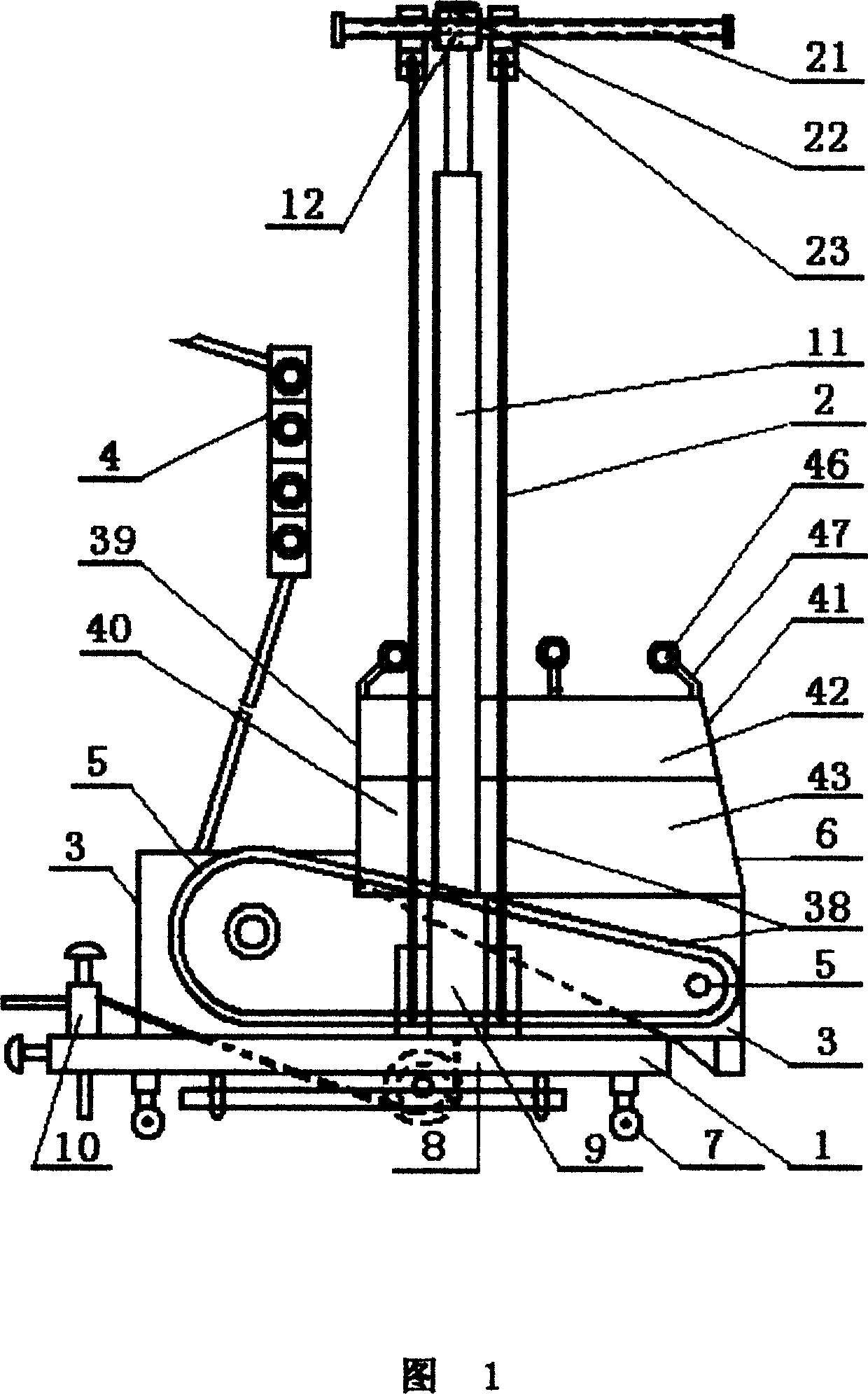
[0026] In Fig. 1, the automatic plastering machine of the present invention is mainly made up of base 1, gantry frame 2, main frame 3, electrical control mechanism 4, transmission mechanism 5 and painting mechanism 6. The main body of the base 1 is in the shape of a square frame, with universal moving feet 7 on the four corners below, a gantry mounting seat 9 near the middle position above the left and right frame edges 8, and a near front position on the left and right frame edges 8 Also be provided with left and right rope tightening device 10 on.

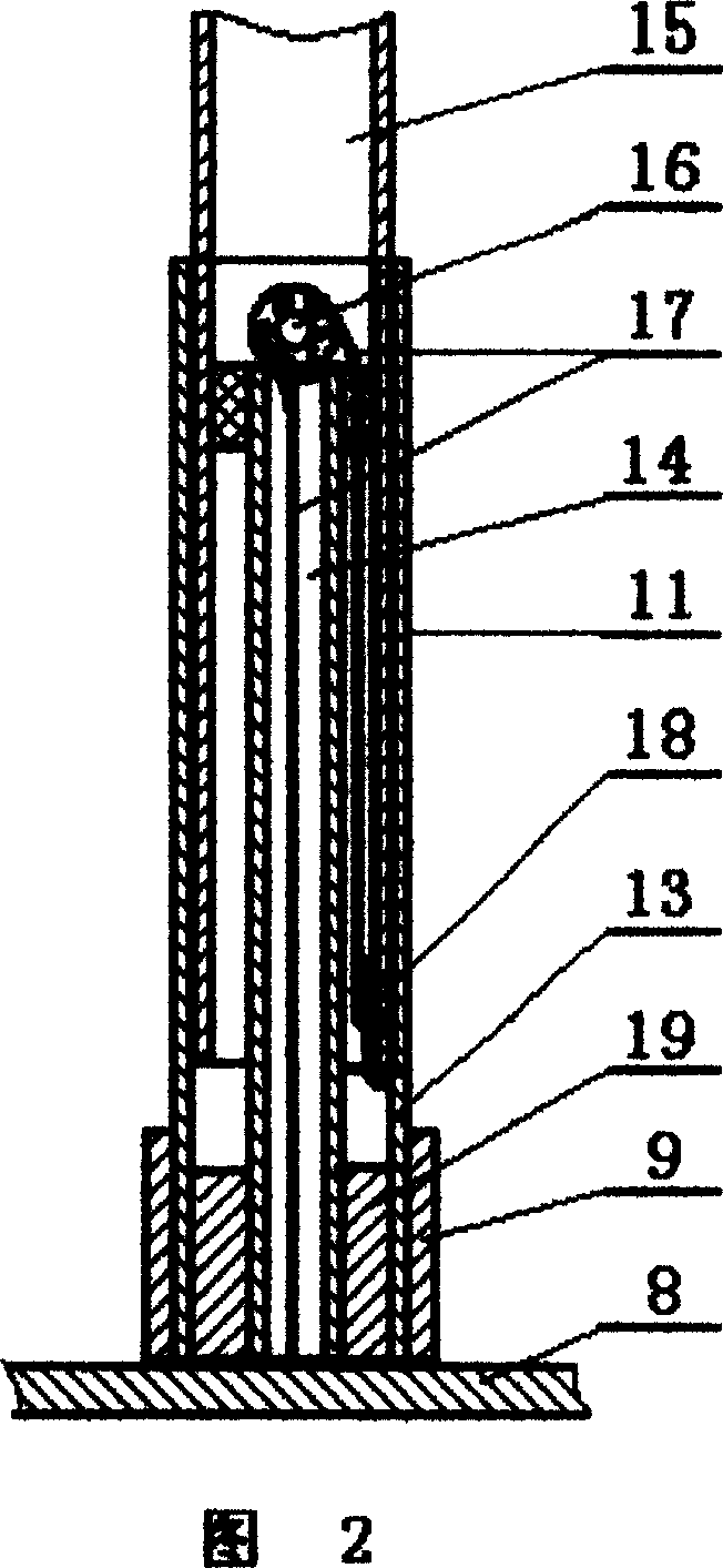
[0027] In Fig. 2, the gantry 2 is mainly composed of left and right columns 11 and beams 12, and the left and right columns 11 are assembled by a stroke tube 13, a standpipe 14, and a lift tube 15 which are mutually nested. The standpipe 14 is located at the innermost, and a steel wire pulley 16 i...


PUM


Abstract

This invention relates to one automatic printing machine, which comprises bottom socket, gate rack, main frame, control structure, drive structure and printing structure, wherein, the bottom socket is set with direction move leg, gate rack and left and right tightening rope; the gate rack is composed of process tube, stand tube, lift tube cover, left and right column with contract function and printing thickness adjust structure with prompt thickness adjusting function, top limit parts against position wall function and beam hanging from main frame; the control structure is formed by process switch with overflow protection function; the materials bin is formed by basic bin and aid bin; the aid bin is set on bin formed by side board to add materials volume to top position.

Description

technical field [0001] The invention relates to a building construction equipment, in particular to an automatic plastering machine which is easy to move. Background technique [0002] In the construction industry, the plastering of walls after building is a troublesome construction operation. For a long time, manual methods, scaffolding, and high-altitude operations have been used. In addition to high risk, high work intensity, and waste of materials, the efficiency is low and the quality is low. Difficult to control and thus poor economics. In recent years, an automatic wall plastering machine has appeared, which has the function of automatically raising and plastering the wall, greatly reduces the intensity of manual work, improves work efficiency, and has certain practicability. However, the actual use of this type of machine proves that there are many flaws in the ointment: one is that the main body of the rack is fixed in overall height, and cannot freely enter and ex...

Claims


Application Information

Patent Timeline
Patent Type & Authority Applications(China)
IPC IPC(8): E04F21/08
Inventor 王耀刚
Owner SHANGHAI DARONG MACHINERY DEVICE
Why Eureka
Try Eureka