

Capacity controlled compressor with one and two cylinders
A two-cylinder compressor, capacity control technology
- Summary
- Abstract
- Description
- Claims
- Application Information
AI Technical Summary
Problems solved by technology
Method used
Image

Examples
Embodiment 1
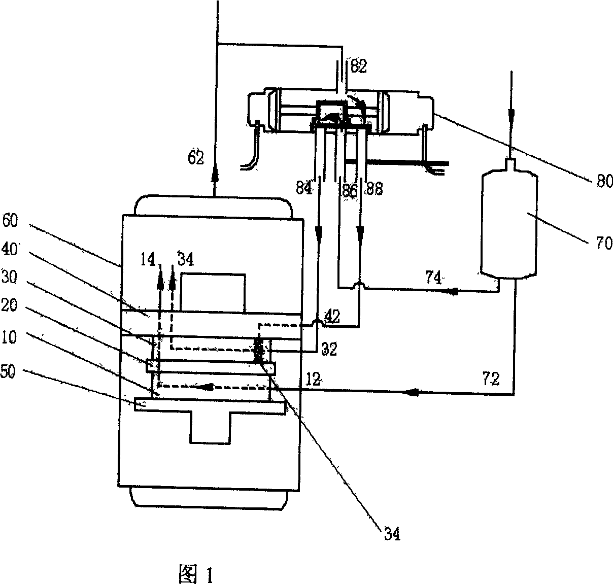
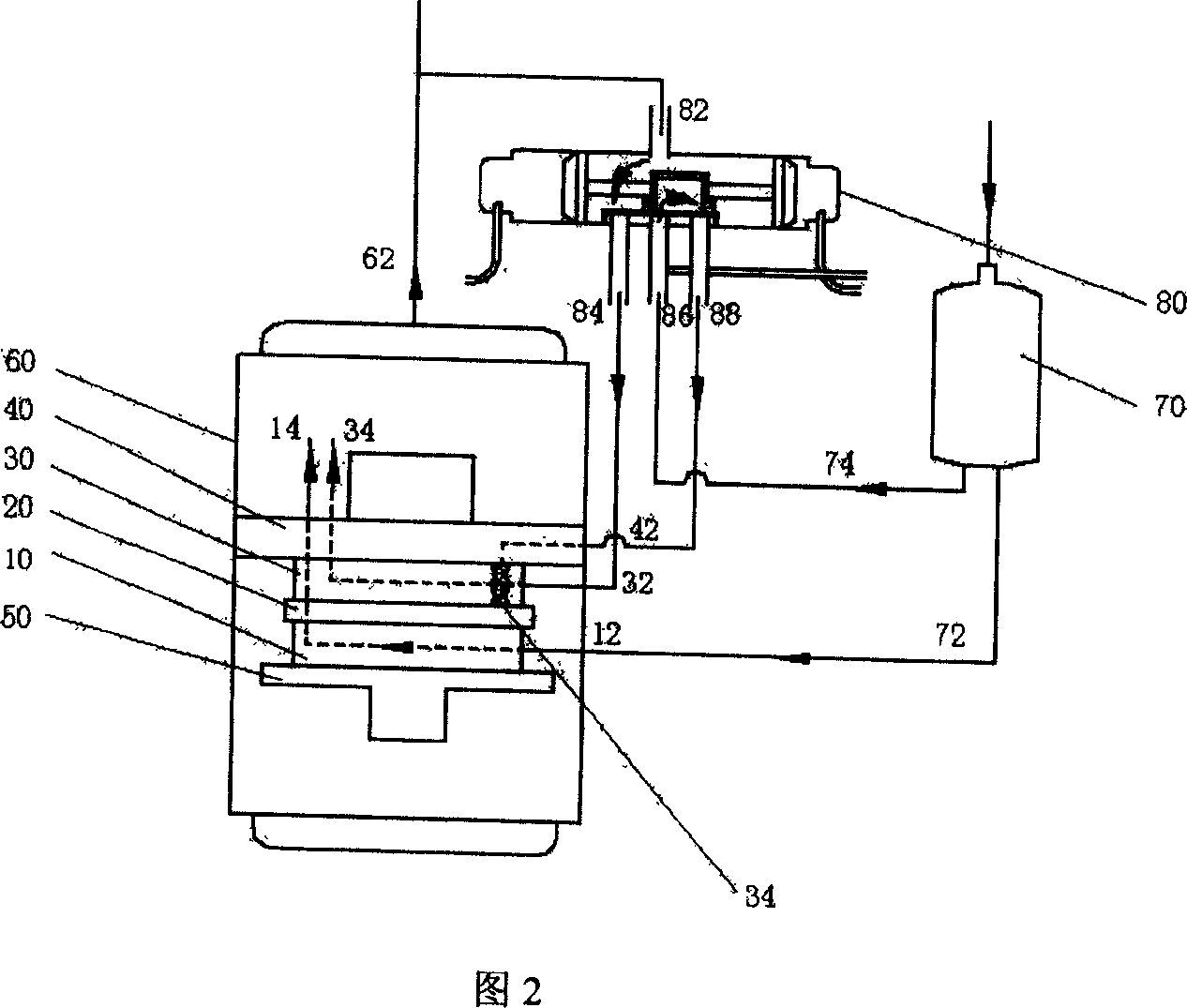
[0018] Embodiment 1: It can be switched between two states of double-cylinder parallel compression, upper cylinder idling, and lower cylinder single-cylinder compression, and outputs the sum of the displacement of the two cylinders or the displacement of the lower cylinder, (see Figure 1-2 ).
[0019] Its characteristics are: it is composed of a compressor with double cylinders 10 and 30 with double suction pipe accumulator 70 connected to a four-way valve 80, and the vane chamber 36 of the upper cylinder 30 of the two-cylinder compressor is sealed Type structure, in the double suction pipe accumulator 70, the air ports 32, 12 of the upper and lower cylinders 30, 10 of the compressor, the airtight blade cavity 36 of the upper cylinder and the high pressure exhaust pipe 62 pass through the four The connection control of the through valve 80 uses the gas pressure difference between the vane chamber 36 and the suction chamber 33 to control the vane 31 of the upper cylinder to con...
Embodiment 2
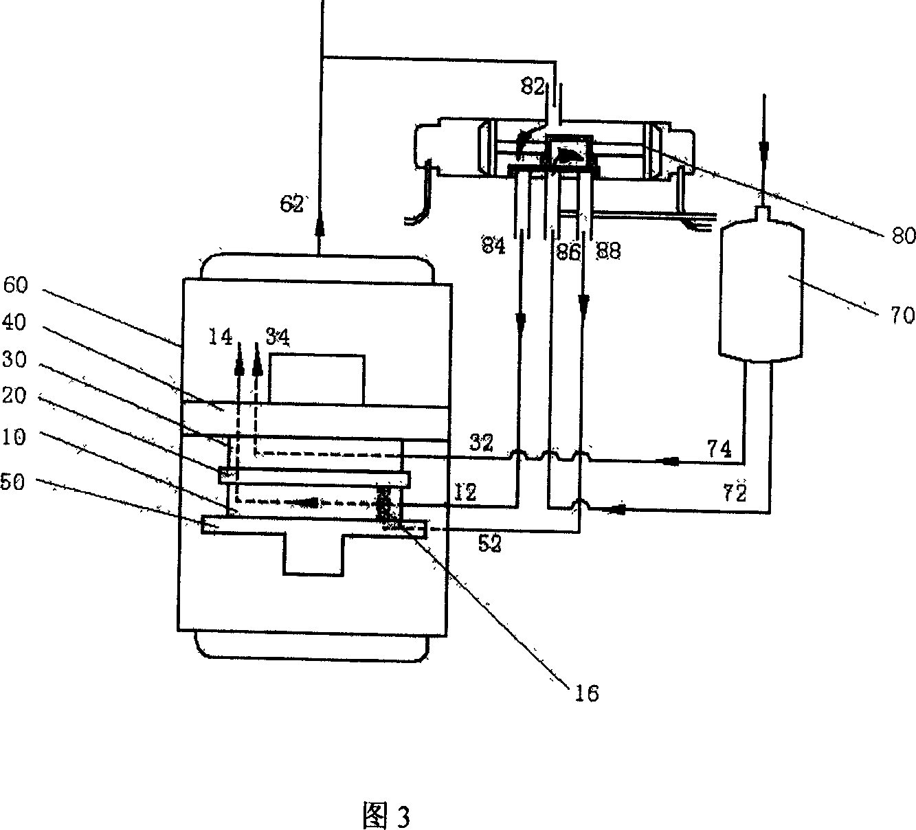
[0027] Embodiment 2: It can be switched between two states of double-cylinder parallel compression and lower cylinder idling, and upper cylinder single-cylinder compression, and outputs the sum of the exhaust volumes of the two cylinders or the exhaust volume of the upper cylinder, (see Figure 3).
[0028] It is characterized in that it is composed of a compressor with double cylinders 10 and 30 with double suction pipe accumulators 70 connected to a four-way valve 80, and the vane chamber 16 of the lower cylinder 10 of the two-cylinder compressor adopts a closed type structure. The connection method is: one outlet 74 of the liquid accumulator 70 is connected with the suction port 32 of the upper cylinder, and the exhaust port 34 of the upper cylinder enters the compressor housing 60; the other outlet 72 of the liquid accumulator is connected with the four-way valve The four-way valve pipe 84 is connected to the suction port 12 of the lower cylinder, and the exhaust port 14 of...
Embodiment 3
[0030] Embodiment 3: It can switch among the three states of single-cylinder compression of the upper cylinder or single-cylinder compression of the lower cylinder, or parallel compression of two cylinders, and output the exhaust volume of the upper cylinder or the exhaust volume of the lower cylinder, or the exhaust volume of the two cylinders. For the sum of air volumes, see Figure 4-6.
[0031] It is characterized by a compressor with double cylinders 10 and 30 connected with two four-way reversing valves 80 and 90 with double suction pipe accumulator 70, and the vane cavities of the two cylinders are all closed structures. And the suction holes in the two cylinders and the airtight vane cavity are connected with the two four-way valves respectively.
[0032] Suppose: a state A of the four-way valve 80 is that the pipe 84 is connected with the pipe 86, and the pipe 82 is connected with the pipe 88; another state B is that the pipe 82 is connected with the pipe 84, and the p...
PUM
 Abstract
Description
Claims
Application Information