Micro-gap transmission

A technology of transmission and micro-gap, which is applied in the direction of transmission, transmission parts, gear transmission, etc., can solve the problems of high processing precision of gears and shafts, transmission angle error, etc., and achieve small transmission error, simple structure, and easy manufacturing and the effect of simple assembly process

Inactive Publication Date: 2007-03-07
吴琼海
View PDF0 Cites 6 Cited by
  • Summary
  • Abstract
  • Description
  • Claims
  • Application Information

AI Technical Summary

Problems solved by technology

Existing gearboxes usually use a key or spline connection to connect the shaft to the gear. Therefore, the machining accuracy of the gear and the shaft is high. Considering the processing and assembly p

Method used


Image

  • Micro-gap transmission
  • Micro-gap transmission
  • Micro-gap transmission

Examples


Embodiment Construction

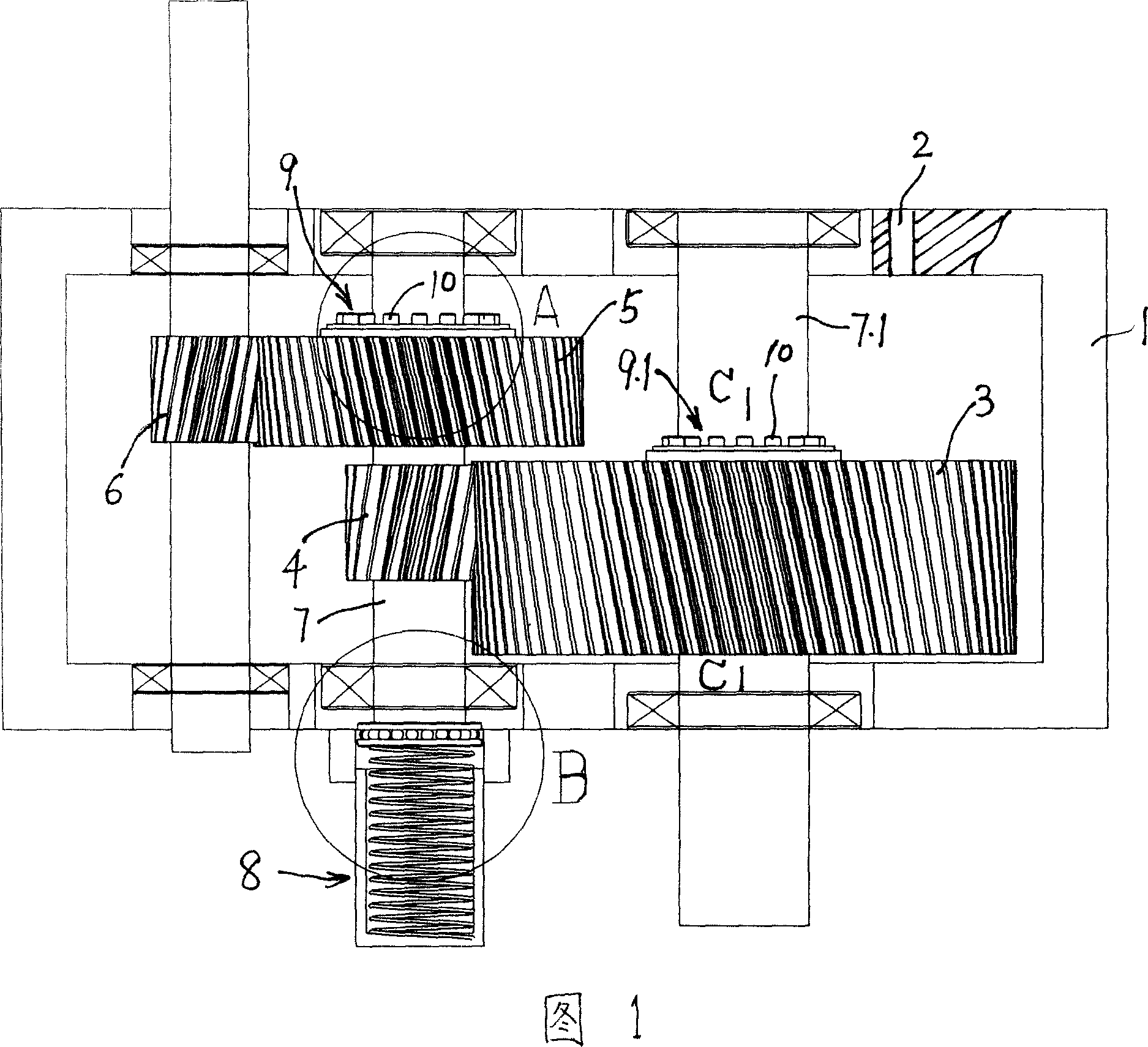
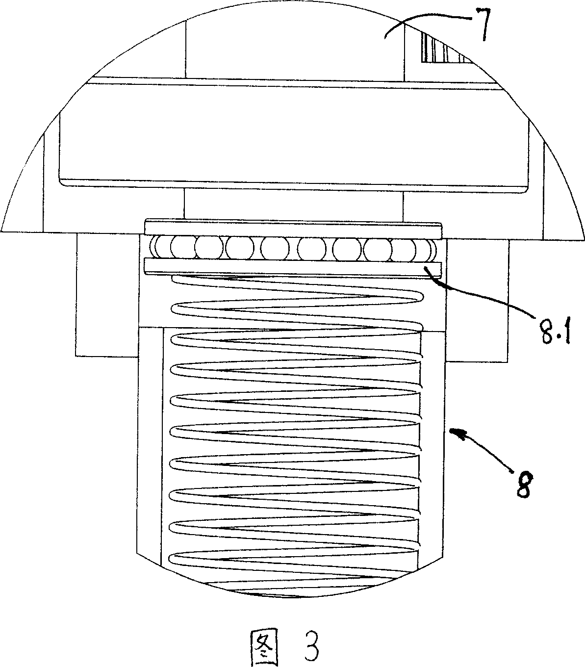
[0015] Referring to FIG. 1 to FIG. 4 , the present invention will be further described in detail below in conjunction with embodiments. The micro-gap transmission device of the present invention includes: a box body 1 and gears 3, 4, 5, 6 that mesh with each other, and its unique feature is that the elastic member 8 pushes the gear shaft 7 from one axial end to the other end shaft shoulder or shaft end.

[0016] There is preferably a bearing 8.1 between the elastic member 8 and the shaft shoulder or shaft end.

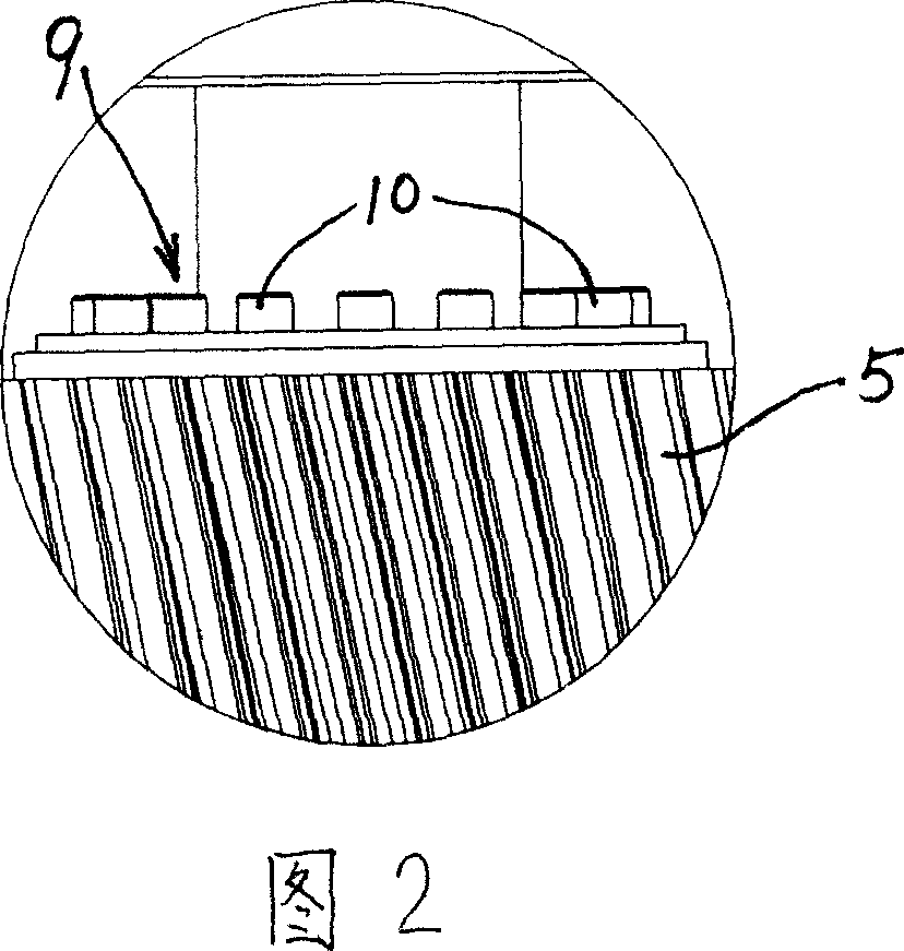
[0017] A further technical solution may be: the gear shafts 7, 7.1 are connected to the gears 5, 3 through tension couplings 9, 9.1. Specifically, between the gears 5, 3 and the gear shafts 7, 7.1, the bolts 10 tighten the conical tension rings 11 located on both sides, and the gears are squeezed under the extrusion of their mutually matching conical surfaces. 5 and 3 are fastened together with the gear shafts 7 and 7.1 respectively.

[0018] When assembling, in ord...


PUM


Abstract

This invention relates to micro gap drive device, which comprises case and meshed gear and is characterized by spring parts with one end push other end along gear axis. This invention has the following advantages as a, micro gap between motor switch with high accuracy; b, simple process and matching for widely application.

Description

technical field [0001] The invention relates to a micro-gap transmission device, which is mainly used for speed-up or speed-down transmission. Background technique [0002] Due to the increasing automation of industrial control, the gear reduction box has the advantages of large speed ratio, large output torque, small size and high efficiency. However, ordinary gearboxes have 3 or 4 pairs of gears engaged in meshing at the same time. Existing gearboxes usually use a key or spline connection to connect the shaft to the gear. Therefore, the machining accuracy of the gear and the shaft is high. Considering the processing and assembly process requirements, a gap must be left. During the transmission process, when When the input end changes the direction of rotation, there will be a transmission angle error at the output end due to clearance. For such structures, see the "Machine Design Handbook" published by Machinery Industry Press. Contents of the invention [0003] The o...

Claims


Application Information

Patent Timeline
IPC IPC(8): F16H1/20F16H57/12F16H55/18
Inventor 吴琼海
Owner 吴琼海
Why Eureka
Try Eureka