Damper rail

A track and body technology, applied in the track field, can solve the problems of limited effective working area of ​​damping materials, limited vibration and noise reduction, and the track cannot achieve the effect of vibration and noise reduction, and achieves good vibration and noise reduction. And the effect of wheel wear and increase of effective contact area

Active Publication Date: 2007-03-14
QINGDAO CREATE ENVIRONMENT CONTROL TECH
View PDF1 Cites 37 Cited by
  • Summary
  • Abstract
  • Description
  • Claims
  • Application Information

AI Technical Summary

Problems solved by technology

However, since the damping body consumes rail vibration energy by generating shear-based resistance that is opposite to the forced direction of the vibration, its vibration and noise reduction performance and the contact area between the damping body and the rail, that is, the damping body withstands shear The actual working area of ​​the shear force is roughly proportional. For this reason, the planar plate damping material used in the above-mentioned patent is limited by the size of the rail waist, and the effective working area of ​​the damping material is limited, so the vibration and noise reduction effect it can achieve is also very limited, so this type of track cannot achieve the ideal vibration and noise reduction effect

Method used


Image

  • Damper rail
  • Damper rail
  • Damper rail

Examples


Embodiment 1

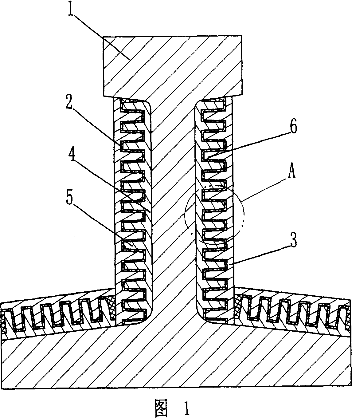
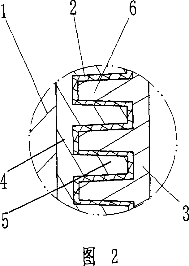
[0031] As shown in Figures 1 and 2, the damping track of the present invention includes a track body 1, a damping body 2 made of high-damping rubber and a steel restraint body 3, and a steel rail is also arranged between the track body 1 and the damping body 2. Connecting body 4, connecting body 4 is multi-point welded on the non-working surface of track body 1 both sides by resistance welding, for the convenience of construction, the connecting body is divided into two sections according to its shape change on each side of track body and installed. The connecting body 4 and the damping body 2 have a trapezoidal rib 5 on the side adjacent to the damping body 2, and the trapezoidal rib 6 interlaced with the connecting body trapezoidal rib 5 is arranged on the side adjacent to the damping body 2, and the damping body 2 It is arranged in the matching gap between the connecting body 4 and the constraining body 3, and the connecting body 4 and the constraining body 3 are vulcanized ...

Embodiment 2

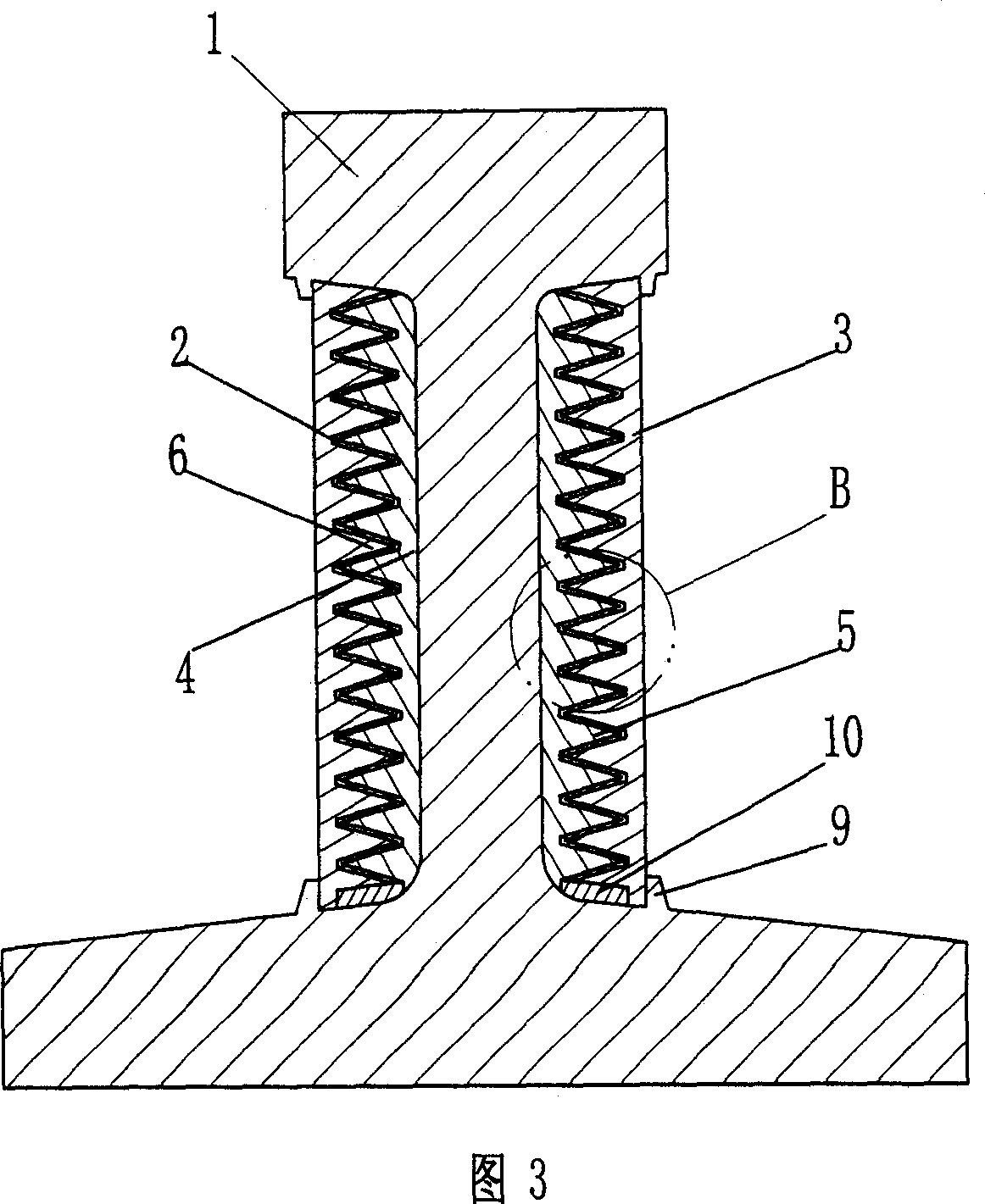
[0035]As shown in Fig. 3 and Fig. 4, the damping track of the present invention comprises a track body 1, a damping body 2 made of modified damping asphalt which is liquid at the working temperature, and an aluminum alloy plate constraining body 3, between the track body 1 and the damping body 2 A connecting body 4 made of aluminum alloy is also provided between them, and the connecting body 4 is firmly bonded to the two sides of the track body 1 by using high-strength damping material. When bonding with high-strength damping materials, the bonding layer should be as thin as possible to ensure high bonding stiffness. The outer surface of the connecting body 4 has triangular ribs 5 , and the side of the constraining body 3 adjacent to the damping body 2 has triangular ribs 6 interlaced with the ribs 5 . The damping body 2 is arranged in the fitting gap between the connecting body 4 and the constraining body 3 . The restraint structure is locked on the rail by means of the groo...

Embodiment 3

[0039] As shown in Figure 5, the damping track of the present invention includes a track body 1, a damping body 2 made of solid modified asphalt, and an aluminum profile constraining body 3, and an aluminum profile connecting body 4 is also arranged between the track body 1 and the damping body 2 , the connecting body 4 is firmly bonded on the track body 1 by using a highly elastic adhesive, and the ribs on the connecting body 4 cross-fit with the hollow rectangular bosses on the constraining body 3, and the damping body 2 is arranged between the connecting body and the restraining body. within the fit gap between bodies.

[0040] In order to facilitate the construction, the corresponding connecting body and restraining body are made in sections according to the shape of the rail. Since the space at the bottom of the rail is small and the plane area of ​​the rail bottom is large, the connecting body is omitted under the rail, and the connecting body is directly installed betwee...


PUM


Abstract

The invention relates to a rail, especially steel rail for railway or electric trolley. Damp rail comprises rail body, on whose non-working surface connector with convex rib or convex-concave structure is set, constraint body connected with rail body, set corresponding to connector, whose inner surface processes convex rib or convex-concave structure and damping body, set between connector and constraint body or among connector, rail body and constraint body, forms labyrinth constraint damping structure, which is set continuously or distantly along length direction of rail body. The rail can decrease shake generated by rail and control the shake and noise of rail in original source, while alleviate availably steel and wheel attrition generated by liberative energy of rail shaking so that there is good damping and noise reduction effect, and operating life of wheel and rail, safety and amenity of train running is largely improved.

Description

technical field [0001] The invention relates to a rail, in particular to a steel rail used for railways or trams. Background technique [0002] With the rapid development of economic construction and transportation infrastructure construction, rail transportation methods such as subway, elevated light rail, ordinary railway and high-speed railway are playing an increasingly important role in the field of freight and passenger transportation because of their advantages of large carrying capacity, convenience, safety and reliability. role. How to reduce the noise pollution during rail transportation, reduce the vibration and wear of rails during transportation, thereby prolonging the life of the rail and improving the safety and comfort of rail transportation has become a difficult problem closely related to the production and life of the people and is increasingly being used. The attention of governments and scientific and technological workers in various countries. In the ...

Claims


Application Information

Patent Timeline
Patent Type & Authority Applications(China)
IPC IPC(8): E01B19/00
CPCE01B19/003
Inventor 尹学军
Owner QINGDAO CREATE ENVIRONMENT CONTROL TECH
Why Eureka
Try Eureka