
Solar vacuum energy exchange thermal-collecting tube

A heat collection tube and vacuum technology, which is applied in the field of solar vacuum energy exchange heat collection tubes, can solve the problems of affecting the reflection effect, large wind resistance, easy to fall ash and dust collection, etc.

Inactive Publication Date: 2013-09-18
ZIBO ENVIRONMENTAL PROTECTION TECH CO LTD +1
View PDF4 Cites 0 Cited by
  • Summary
  • Abstract
  • Description
  • Claims
  • Application Information

AI Technical Summary

Problems solved by technology

Although this structure reduces heat loss to a certain extent, it still cannot solve the problem of heat loss caused by heat radiation in the inner and outer tubes. In addition, since the reflector is arranged outside the outer tube, heat will still be lost in the air. Moreover, it is easy to collect dust and dust, which affects the reflection effect. After a period of use, because the reflection plate will be covered by dust, the reflection effect will gradually weaken, and the heat loss will continue to increase, which cannot solve the problem of large heat loss. , and the wind resistance is large, it is easy to collect snow, and it also causes a certain amount of light pollution
Placing metal reflectors or other reflectors in the vacuum interlayer of the solar vacuum heat collector tube will increase the amount of outgassing, and the vacuum will drop, which will affect its performance

Method used


Image

  • Solar vacuum energy exchange thermal-collecting tube
  • Solar vacuum energy exchange thermal-collecting tube
  • Solar vacuum energy exchange thermal-collecting tube

Examples


no. 1 example

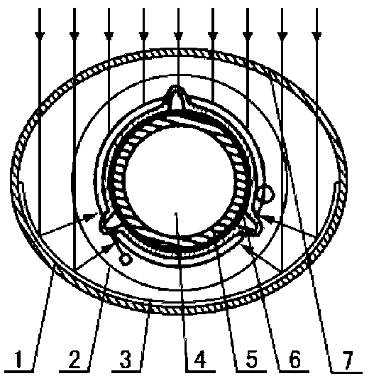
[0067] The first embodiment: a single-pass variable diameter single-layer tube head solar vacuum energy conversion heat collection tube provided by the present invention includes a glass positioning nozzle, 13, an inner energy conversion tube 5 and an outer glass tube, and the solar vacuum energy conversion heat collector The connection seal between the outer glass tube of the heat pipe and the inner transducing tube 5 is provided with a variable-diameter blocking step installation sealing surface with a certain heat insulation function. , between the inner transduction tube 5 and the outer tube is an annular vacuum interlayer 2, the outer wall of the inner transduction tube 5 is coated with a transduction membrane plate 6, and on the inner tube wall of the backlight surface 1 of the outer glass tube of the solar vacuum energy conversion heat collection tube, Composite with a reflective mirror 3, the opening angle of the reflective mirror 3 is ≤180°, and the curved surface refl...

no. 2 example

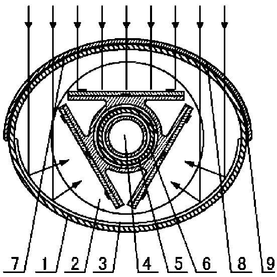
[0068] The second embodiment: the all-glass heat pipe provided by the present invention is equipped with a sealing retaining ring, including heat-conducting working fluid filling and exhaust tailpipe sealing head, heat pipe heat release section 19, metal support bullet clip, and glass explosion-proof safety valve 22. Transducer tube 5, heat exchange medium, glass positioning nozzle 13, variable diameter step mounting sealing surface 14, throttling vapor-liquid heat exchange device 20, transduction membrane plate 6, outer glass tube, and reflective mirror surface 3. The heat-collecting section of the heat-collecting section of the energy-transfer tube 5 with both ends of the glass-welded head is a glass explosion-proof safety valve 22, and the throttling vapor-liquid heat exchange device 20 is positioned concentrically between the heat-collecting section of the energy-transfer tube 5 and the heat pipe through the metal support clip 21. Between the exothermic section 19. One end...

no. 3 example

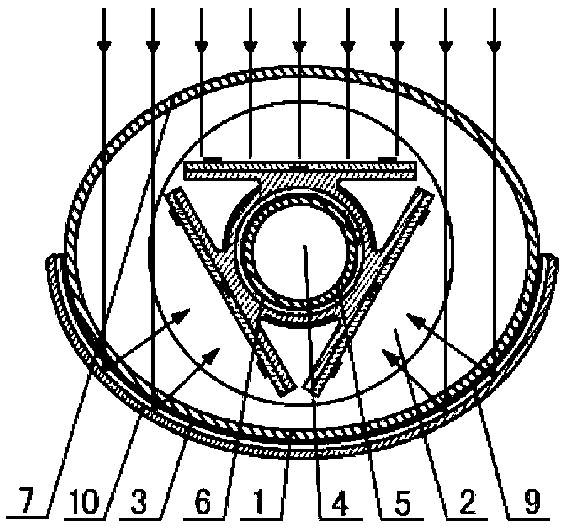
[0070] The third embodiment: on the outer tube wall of the backlight surface 1 of the outer glass tube of the solar vacuum heat collection tube, a reflective mirror surface 3 is bonded and compounded with a transparent glue 9, and the reflective mirror surface 3 is compounded with a composite substrate 10. The elastic electrical connection assembly 15 with a long-lasting getter is sealed and led out through the metal glass sealing head 16 . When in use, the conductor is connected to a DC power supply, so that the conductive heat-absorbing film of the energy conversion tube can be negatively charged, and through induction, the inner wall of the water chamber of the heat collecting tube is charged with positive charges and becomes acidic, preventing metal ions from forming on the inner wall of the heat collecting tube. A photovoltaic cell 18 is compounded on the transducing membrane plate 6 of the transducing tube 5 , and the wires of the photovoltaic cell 18 are sealed and led o...


PUM


Abstract

The invention relates to a vacuum solar collector, comprising outer glass pipe, inner glass pipe and circular vacuum cavity between them. Transduction diaphragm is bonded with outside wall of the inner glass pipe, Variable diameter barrier step assembling sealing face with certain heat insulation performance is set on the sidewall of outer glass pipe or at the connecting sealing position between inner and outer glass pipe of vacuum solar collector. At least one of variable diameters of outer glass pipe is set at the jointing position between inner and outer glass pipe and is joint with reducing diameter of inner glass pipe. Outer sidewall of vacuum solar collector is possibly combined with condenser lens, whose section is ellipse or free-formed surface of closed line made up of curves andarcs. Through the section of condenser lens, vacuum solar collector makes pipe wall with backlight surface combine reflecting surface so that it condenses by reflecting; or by arc fresnel lens, whichis ray-facing surface of outer glass pipe condensing in refraction is accomplished; or reflecting surface with convex-concave groove compounded on backlight surface of circular glass pipe in longitudinal direction, condensing in reflection is completed.

Description

technical field [0001] The invention relates to a solar heat collecting element, in particular to a solar vacuum energy-converting heat collecting tube. Background technique [0002] During the actual use of the solar vacuum heat collector tube, the selective absorption coating coated on the outer wall of the inner tube mainly absorbs and gathers heat. Since there is a vacuum layer between the inner and outer tubes, there is no air convection between the outer tubes to conduct heat. The problem of heat loss to the outer tube has a better heat collection effect. However, since the vacuum layer between the inner and outer tubes cannot prevent radiation heat transfer, part of the heat absorbed by the inner tube will be lost through thermal radiation, resulting in heat loss. Among them, the radiation heat emissivity of the inner tube is about 5-8%, while that of the outer tube is about 90%. Therefore, most of the heat radiated from the inner tube to the outer tube will be radia...

Claims


Application Information

Patent Timeline
Patent Type & Authority Patents(China)
IPC IPC(8): F24J2/05F24J2/24F24S10/40F24S10/70
CPCF24S10/45Y02E10/44
Inventor 徐宝安
Owner ZIBO ENVIRONMENTAL PROTECTION TECH CO LTD
Learn More