Refrigerator

A technology for refrigerators and ice-making trays, which can be used in household refrigerators, ice making, and ice-making, etc. It can solve the problem of reduced removal of ice-making trays, and achieve the effect of improving cooling efficiency and low-cost structure

Inactive Publication Date: 2007-03-14
HITACHI APPLIANCES INC
View PDF1 Cites 6 Cited by
  • Summary
  • Abstract
  • Description
  • Claims
  • Application Information

AI Technical Summary

Problems solved by technology

This is because, when the positional relationship between the outlet and the drive source is not changed as before, and the same series of models with a large depth directi

Method used


Image

  • Refrigerator
  • Refrigerator
  • Refrigerator

Examples


Example Embodiment

[0038] Example 1

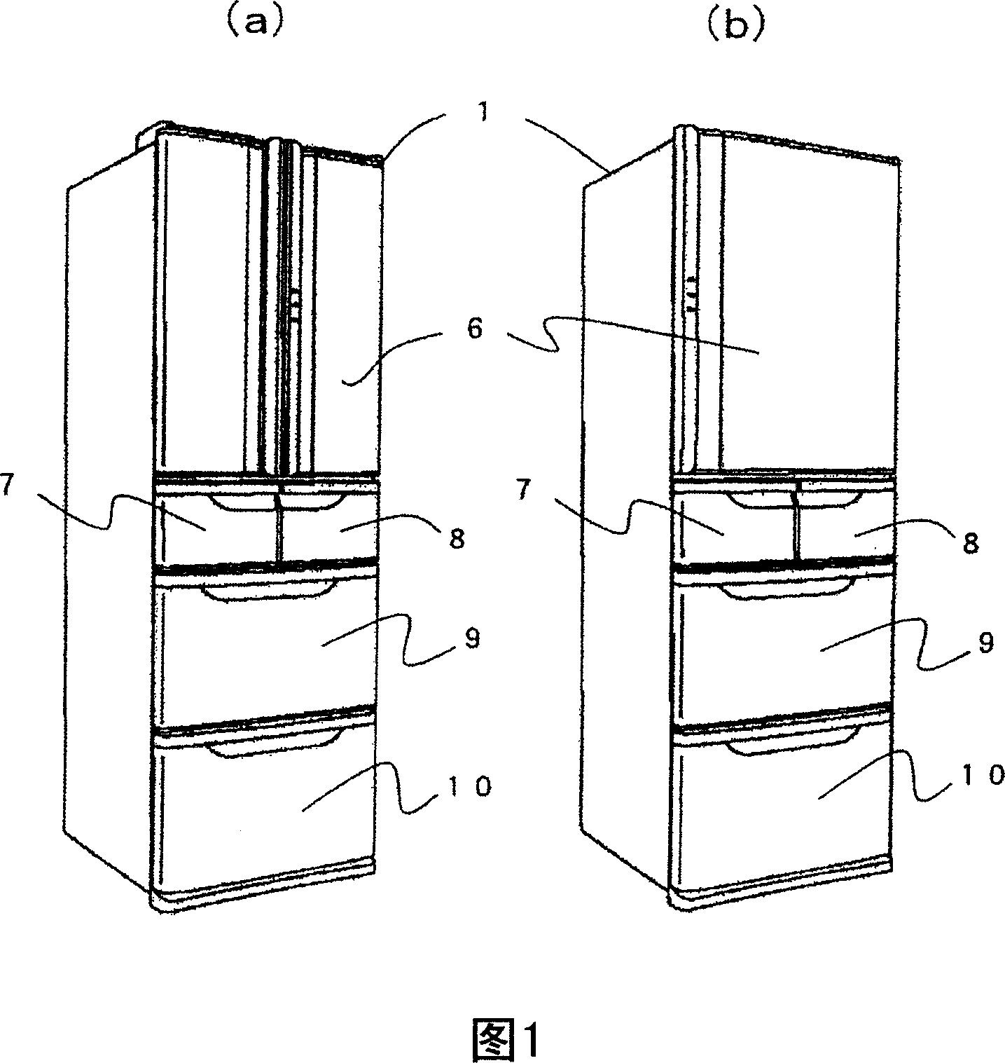
[0039] Fig. 1 is a perspective view of a refrigerator according to Embodiment 1 of the present invention. Figure 1(a) shows a so-called side-by-side refrigerator in which the door 6 covering the front opening of the refrigerating compartment arranged on the uppermost layer is made into a double-opening door. Figure 1(b) shows a single door 6 A refrigerator that covers the front opening of the refrigerator compartment. Either one indicates an example in which a refrigerating room is arranged above the storage room in the freezing temperature zone, and a vegetable room is arranged below, and this embodiment does not distinguish these.

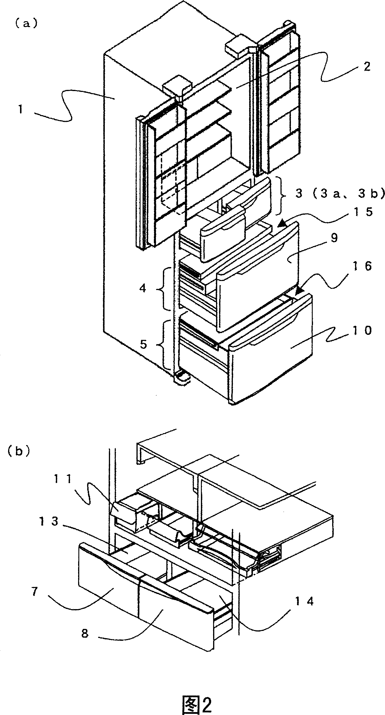
[0040] Fig. 2 is a schematic diagram showing the indoor structure of the refrigerator in the example shown in Fig. 1(a). Fig. 2(a) is a diagram showing the overall structure, and Fig. 2(b) is an enlarged view of the main part.

[0041] The refrigerator 1 of the present embodiment includes a refrigerating compartment 2, an upper fre...


PUM


Abstract

The invention provides a refrigerator with an automatic ice maker whose ice tray is drawable, having inexpensive construction for improving cooling efficiency. The refrigerator comprises the automatic ice maker (12) having a drive part (29) on the inner side of the ice tray (30) and provided in an ice making room (3a). On the upper side of the drive part (29), a communication passage (33) is provided for blowing cold air discharged from the back face of the ice tray (30) forward to the longitudinal direction of the ice tray (30).

Description

technical field [0001] The present invention relates to a refrigerator equipped with an automatic ice making device. Background technique [0002] As a refrigerator equipped with an automatic ice making device, there is known a refrigerator disclosed in Patent Document 1 - Japanese Patent Application Laid-Open No. 2004-271047. In this conventional automatic ice making device, in order to make the ice making tray detachable, the driving source of the ice making tray is arranged behind the ice making tray. In addition, cold air blown from the ice-making compartment fan positioned at the rear of the ice-making compartment is introduced into the ice-making tray through a passage that goes around the driving source. [0003] In the existing automatic ice-making device shown in Patent Document 1, the cold air blown out from the air outlet by the fan in the ice-making compartment is passed through the cold air outlet, the cold air guide port, and the cold air outlet arranged in th...

Claims


Application Information

Patent Timeline
IPC IPC(8): F25D17/08F25D11/02F25C1/10
Inventor 小川真申茂中启介南云博文野村初
Owner HITACHI APPLIANCES INC
Why Eureka
Try Eureka