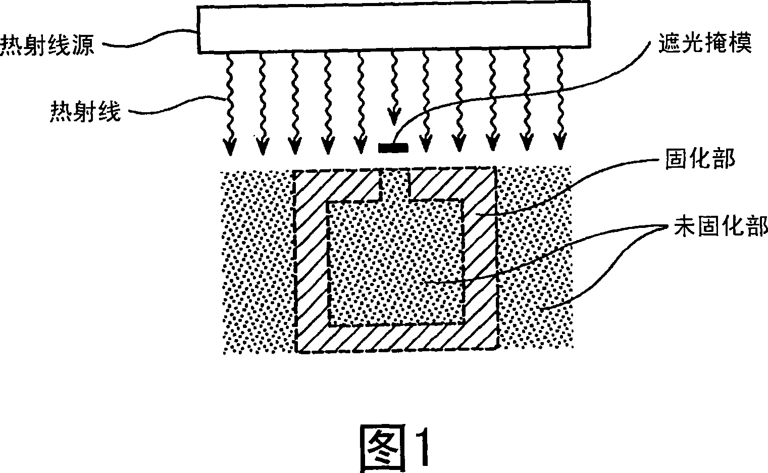
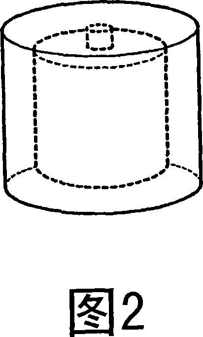
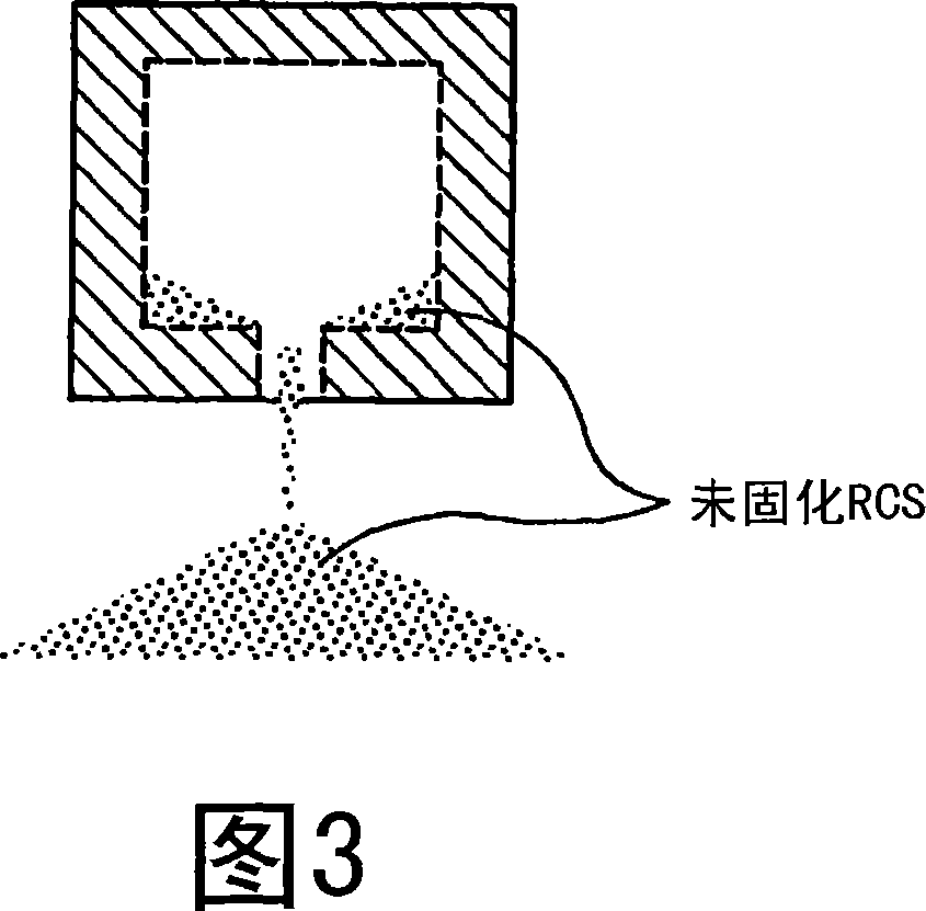
Resin coated sand
A resin coating and coating technology, which is applied to casting molding equipment, molds, cores, etc., can solve the problems of dimensional accuracy, low sphericity of molding sand, poor fluidity, etc., and achieve high mold strength and sand discharge Excellent performance and fluidity
- Summary
- Abstract
- Description
- Claims
- Application Information
AI Technical Summary
Problems solved by technology
Method used
Image
Examples
Example
[0096] Examples 1-2 and Comparative Examples 1-4
[0097] (1) Manufacture of RCS
[0098] As the molding sand, the molding sand obtained above and Flattery Silica were used. Their chemical compositions are shown in Table 1. In Table 1, Flatelli silica sand is conventional amorphous silica sand, and fired famulite sand and electric fusion sand correspond to conventional spherical molding sand.
[0099] RCS was manufactured using the molding sand shown in Table 1 and the various components of the binder composition shown in Table 2 at the ratios shown in Table 2. Specifically, after heating the molding sand at 150° C., 1.0 parts by weight of a phenolic resin (AV Light, Asahi Organic Materials Co., Ltd.) was added to 100 parts by weight of the molding sand and kneaded. Next, the temperature was lowered to 105° C., and at this temperature, 0.83 parts by weight (0.15 parts by weight in terms of solid content) of an aqueous hexamethylenetetramine solution (curing agent, concentra...
Example
[0110] Embodiment 3~4 and comparative example 5~6
[0111] Using the molding sand in Table 1, RCS coated with resin in the same manner as in Example 1 was used to obtain molds with the composition in Table 4, and casting experiments were performed on each of them. First, using RCS, fired at 250°C for 90 seconds to form a test core mold. Set the test core in the main mold of another shape, and cast the melt of cast iron (FC2000) at about 1470°C. After casting and cooling (after standing for 2 hours after the end of casting), the mold was observed for cracking. Afterwards, the mold was disintegrated by beating the core, and the veined casting scars and sintering on the core surface were observed. The results are shown in Table 4. In addition, in Table 4, "◯" of mold cracking means that there was no mold cracking, and "X" means that mold cracking occurred. In addition, "○" of the vein scar means that there is no vein scar, "△" means that the vein scar is slightly generated, and...
Example
[0113] Embodiment 5 and comparative examples 7,8
[0114] RCS was produced by the following method, and evaluated by the following method. The results are shown in Table 6.
[0115] (1) Manufacture of RCS
[0116] The spherical molding sand of the present invention product 2 of Table 5 obtained by the same manufacturing method (flame melting method) as the present invention product 1 of Table 1, and the fired famullite sand B of Table 5 obtained by the firing method were used. In these molding sands, RCS was manufactured by the same method as Example 1 etc. except having used the component shown in Table 6 in the quantity shown in Table 6. In addition, in Table 6, the phenolic resin B is a novolak type phenolic resin, and it made the melting temperature of RCS into 110 degreeC. This melting temperature is measured based on JACT test method C-1 (melting point test method).
[0117] (2) Evaluation
[0118] (2-1)
[0119] The bending resistance was measured using the same m...
PUM
| Property | Measurement | Unit |
|---|---|---|
| The average particle size | aaaaa | aaaaa |
| Surface roughness | aaaaa | aaaaa |
| Surface roughness | aaaaa | aaaaa |
Abstract
Description
Claims
Application Information
 - R&D
- Intellectual Property
- Life Sciences
- Materials
- Tech Scout
- Unparalleled Data Quality
- Higher Quality Content
- 60% Fewer Hallucinations
Browse by: Latest US Patents, China's latest patents, Technical Efficacy Thesaurus, Application Domain, Technology Topic, Popular Technical Reports.
© 2025 PatSnap. All rights reserved.Legal|Privacy policy|Modern Slavery Act Transparency Statement|Sitemap|About US| Contact US: help@patsnap.com


