Magnetic attraction floor

A floor and magnetic suction technology, applied in the field of magnetic suction floors, can solve the problems of cumbersome installation, lack of modification flexibility, and high cost, and achieve the effects of convenient partial or overall replacement, reduction of regular renovation costs, and easy floor laying.

Inactive Publication Date: 2007-03-21
张连墩
View PDF4 Cites 5 Cited by
  • Summary
  • Abstract
  • Description
  • Claims
  • Application Information

AI Technical Summary

Problems solved by technology

When decorating with materials such as cement or lime (sand) slurry, adhesives, screws, etc., not only lack of acquired modification flexibility, but also have their own limitations, such as cement or lime (sand) slurry is only suitable for tiles and stone; adhesives, screws It is only suitable for the decoration of wood boards, plastic boards (bricks), aluminum and aluminum alloy boards, stainless steel boards, etc., and a large amount of adhesives may emit irritating harmful or unpleasant odors; use existing floor keel fixing materials And technology, although it can improve the flexibility of modification, in addition to the limitation that they are only applicable to wooden floors and plastic floors, there are many other problems, such as complex structure, complicated installation; some use steel materials, the cost is too high, etc.

Method used


Image

  • Magnetic attraction floor
  • Magnetic attraction floor
  • Magnetic attraction floor

Examples


Embodiment 1

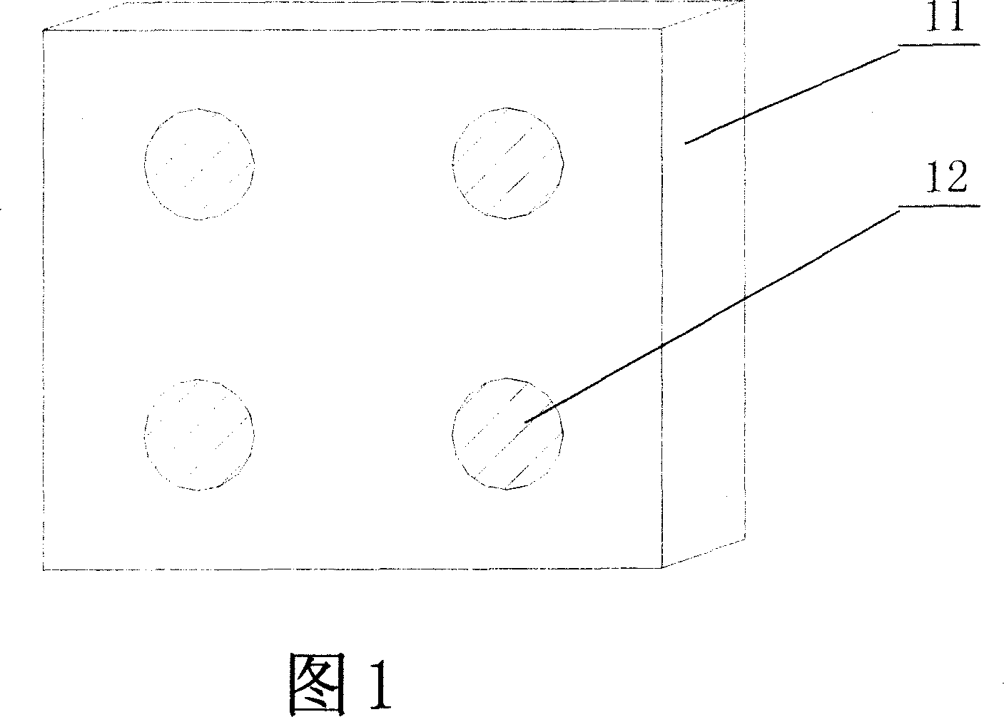
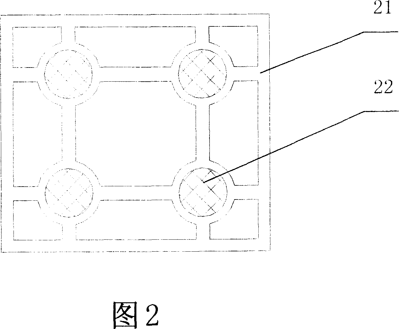
[0034] Please refer to Figure 1 and Figure 2. In Fig. 1, four grooves (φ=32mm, deep H=1.3mm) on the lower plane of the porcelain floor tile 11 with a specification of 200mm×200mm×7mm are equipped with φ=30mm and four iron sheets 12 with a thickness of 1.2mm. The porcelain floor tile 11 is bonded to the iron sheet 12 with an adhesive, and the outer plane of the iron sheet 12 is on the same level as the lower plane of the porcelain floor tile 11 . In Fig. 2, the outer frame specification is 200mm * 200mm * 35mm four grooves (φ = 25mm, deep H = 15mm) on the floor base 21 are equipped with four pieces of said iron sheets that are flat with the porcelain floor tile 11 12 corresponding four permanent magnets 22. The permanent magnet is ferrite with φ=23mm and height h=14.5mm; the skeleton thickness of the floor base 21 is 20mm, and its material is PVC plastic. When laying the floor, the floor base 21 is fixed on the ground smoothly with cement mortar, and then the four iron sheets...

Embodiment 2

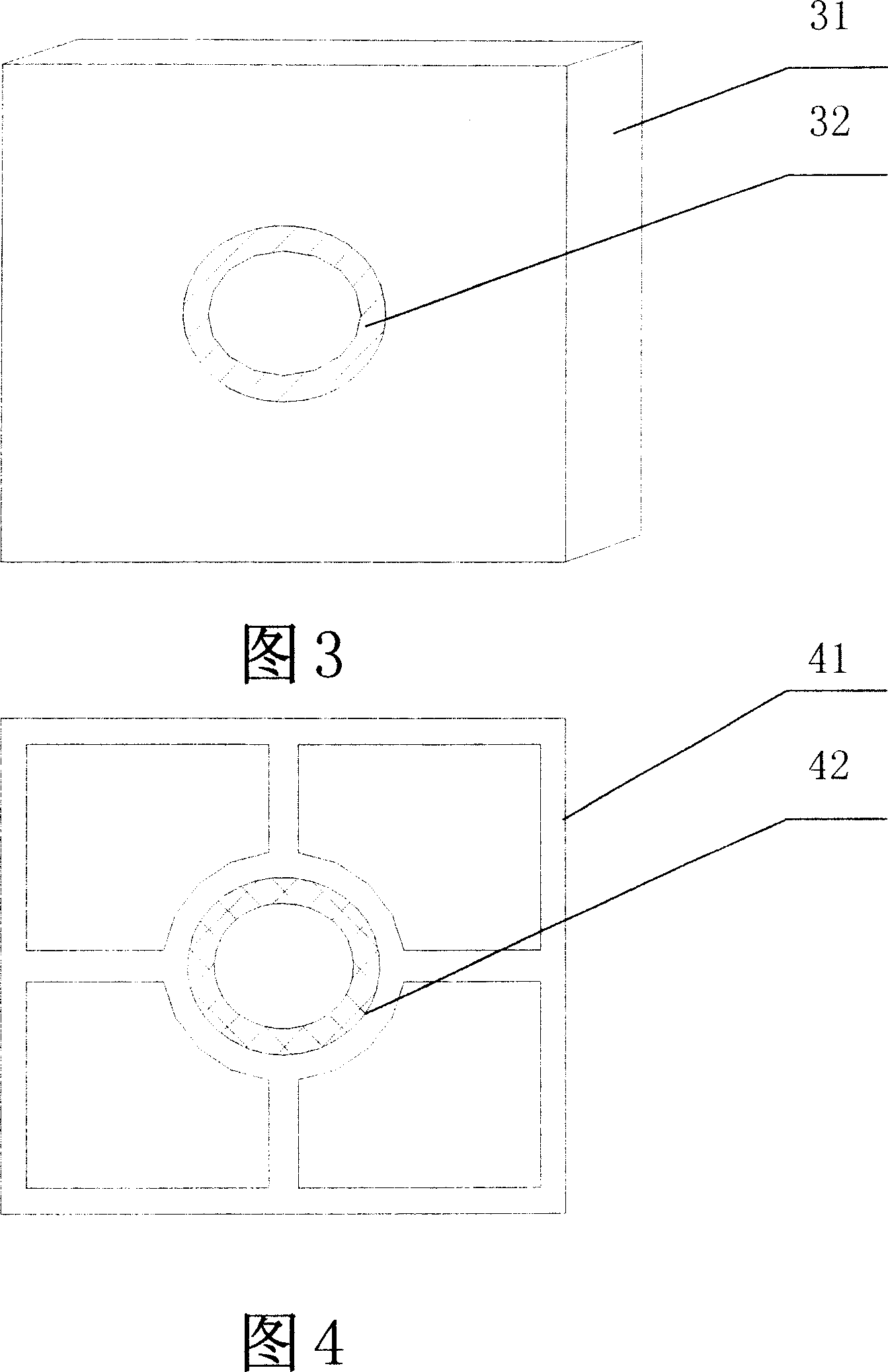
[0036]Please refer to Figure 3 and Figure 4. In Fig. 3, the specification is a groove (φ 外 =64mm, φ 内 =50mm, depth H=1.3mm) is equipped with a φ 外 =62mm, φ 内 =52mm, thickness is 1.2mm iron sheet 32, described porcelain floor tile 31 and described iron sheet 32 ​​adopt adhesive bonding, and the outer plane of described iron sheet 32 ​​and the lower plane of described porcelain floor tile 31 are on the same horizontal plane. In Fig. 4, the outer frame specification is the groove (φ 外 =62mm, φ 内 =52mm, deep H=8mm) a permanent magnet 42 corresponding to a piece of iron sheet 32 ​​on the lower plane of the porcelain floor tile 31 is housed. The permanent magnet is of specification φ 外 =60mm, φ 内 =54mm, height h=7.5mm NdFeB; the skeleton thickness of the floor base 41 is 20mm, and its material is PVC plastic. When laying the floor, first fix the floor base 41 on the ground smoothly with cement mortar, and then install a piece of the iron sheet 32 ​​on the lower plane of the ...

Embodiment 3

[0038] Please refer to Figure 5 and Figure 6. In Fig. 5, the two opposite sides of the solid wood floor 51 with a specification of 200mm x 200mm x 20mm each have a notch equipped with an iron sheet 52 with a specification of 60mm x 15mm x 1mm, and the outer plane of the iron sheet 52 is in contact with the floor 51. The side planes are on the same horizontal plane, and the lower end surface of the iron sheet 52 is on the same human level as the lower plane of the floor 51 . There is a notch on the other two opposite sides of the floor 51 to house a permanent magnet 53, the permanent magnet is a ferrite with a specification of 50mm×13mm×8mm, and the outer plane of the permanent magnet 53 is in line with the The side plane of the floor 51 is on the same horizontal plane, and the lower end surface of the permanent magnet 53 is on the same human level as the lower plane of the floor 51 . In Fig. 6, the outer frame specification is 200mm * 200mm * 35mm. The floor base 61 is equipp...


PUM


Abstract

The present invention relates to a kind of magnetic attraction floor boards which are mutually connected by utilizing magnetic force. Said magnetic attraction floor board is composed of floor board, floor board base seat, permanent magnet and iron sheet. Said invention also provides the concrete structure of said magnetic attraction floor board and its concrete construction method and steps.

Description

technical field [0001] The invention relates to the application of permanent magnet materials in the field of building decoration, in particular to a magnetic floor. Background technique [0002] With the development of social economy and the improvement of human living standards, building decoration has been paid more and more attention by people, and the decoration of floors, wall panels and ceilings of various materials has emerged as the times require. At present, the floor decoration materials and technologies adopted mainly include cement (sand) slurry, lime (sand) slurry, adhesive, screw, embedded, and fixed connection with floor keel (as disclosed Chinese patent: CN200420093119.x / CN03230816.7 / CN03275755.7 / CN200320120425.3) etc. When decorating with materials such as cement or lime (sand) slurry, adhesives, screws, etc., not only lack of acquired modification flexibility, but also have their own limitations, such as cement or lime (sand) slurry is only suitable for ...

Claims


Application Information

Patent Timeline
Patent Type & Authority Applications(China)
IPC IPC(8): E04F15/02E04F13/30
Inventor 张连墩
Owner 张连墩
Why Eureka
Try Eureka