Air conditioner and method for assembling the same

A technology for air conditioners and filters, applied in the field of indoor units, can solve problems such as poor installation, disengagement of air filters, and increased interval between filter guides and the like

Inactive Publication Date: 2007-03-21
FUJITSU GENERAL LTD
View PDF2 Cites 22 Cited by
  • Summary
  • Abstract
  • Description
  • Claims
  • Application Information

AI Technical Summary

Problems solved by technology

[0015] However, for example, in the case where both ends of each filter guide (guide frame) are fixed without being fixed at a central position thereof, when the air filter is inserted, the air filter forcibly opens the filter guide. (guide frame) so that the spacing between the filter guides (guide frame) increases
As a result, the air filter may be disengaged from the filter guide (guide frame), and thus poor installation may occur when the user performs air filter installation

Method used


Image

  • Air conditioner and method for assembling the same
  • Air conditioner and method for assembling the same
  • Air conditioner and method for assembling the same

Examples


no. 1 approach

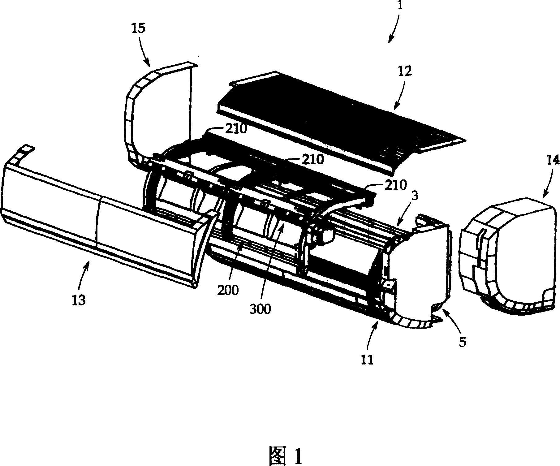
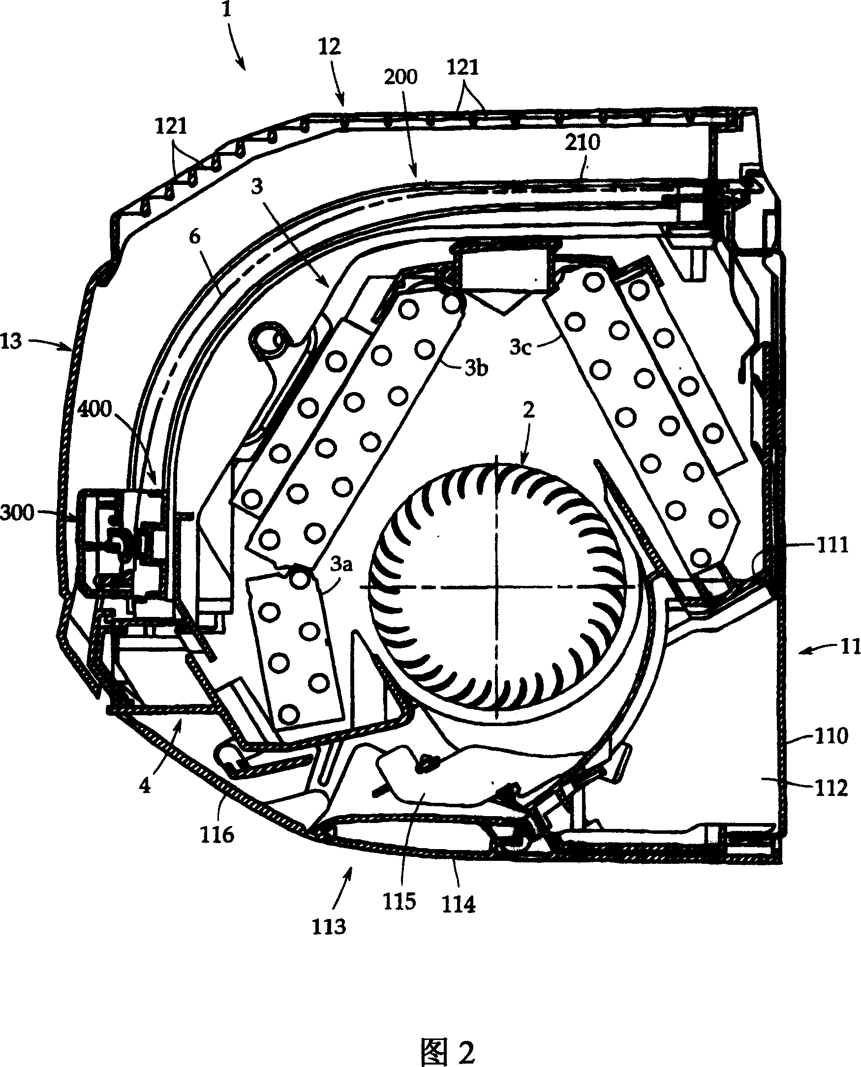
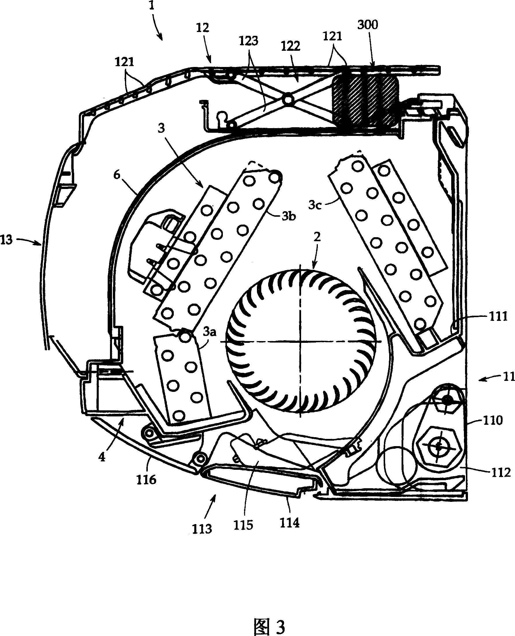
[0160] Hereinafter, embodiments of the present invention will be described with reference to the drawings. FIG. 1 is an exploded perspective view of an air conditioner according to an embodiment of the present invention. Fig. 2 is a longitudinal sectional view of the air conditioner.

[0161] As can be seen from Fig. 1 and Fig. 2, the fuselage casing 1 of this air conditioner comprises: the back plate 110, the base plate 11, the upper panel 12, the front panel 13, the right side that are fixed on the wall with fixing screws (not shown). Panel 14, and left side panel 15. All these parts are molded problowers of synthetic resin. The fuselage shell is combined with a transverse air flow fan 2 as a fan, a heat exchanger 3, a drain pan 4, and the like.

[0162] The base plate 11 is fixed to the back plate 110 with a pair of left and right side plates (not shown) formed to hang from both sides of the heat exchanger 3 to the wall. Between the side plates, a cross-flow fan 2 and a...

no. 2 approach

[0235] In addition, FIG. 18 is a perspective view of a second embodiment of an air conditioner according to the present invention. FIG. 19 is a diagram for explaining a second embodiment of the present invention; FIG. 19A is a first sectional view thereof, and FIG. 19B is an enlarged view of an essential part thereof. Fig. 20 is a second sectional view of a second embodiment of the air conditioner according to the present invention. Fig. 21 is a third sectional view of the second embodiment of the air conditioner according to the present invention. Fig. 22 is a diagram for explaining a third embodiment of an air conditioner according to the present invention; Fig. 22A is a first sectional view thereof, and Fig. 22B is an enlarged view of an essential part thereof. Fig. 23 is a second sectional view of a third embodiment of the air conditioner according to the present invention. Fig. 24 is a third sectional view of a third embodiment of the air conditioner according to the pr...

no. 3 approach

[0255] Now, referring to FIG. 8 and FIGS. 22 to 25 , a description will be given of the configuration and operation as a third embodiment in which the upper panel 1001 b is forcibly opened outward in contact with the dust removing device 1007 .

[0256] As can be seen from FIG. 22A which is the first state, the dust removal device 1007 is configured with a dimension A from the air filter 1004 to the outside of the dust removal device 1007 housing. The dust remover 1007 is accommodated within the range of dimension B from the opposing air filter 1004 to the front panel 1001a, opposite to the lower end of the front of the air filter 1004, in a relationship of "dimension A

[0257] The upper panel 1001b is changed so that it can move vertically through the link mechanism 1010 provided on both sides of the upper panel 1001b, so that the dust removal device does not contact it.

[0258] In addition, the upper panel 1001b is mounted on the upper portion of the air cond...


PUM


Abstract

An air conditioner having a main body is provided with a panel (1001) including a front panel (1001a) a and a top panel (1001b), the main body incorporating an air passage connecting an air inlet (1002) and an air outlet (1003) , an air filter (1004), a heat exchanger (1005), a blower fan (1006), and a dedusting device (1007) attached to the front face of the air filter (1004) which is reciprocated along the surface of the air filter (1004), the top panel (1001b) is opened/closed as the dedusting device (1007) is reciprocated.

Description

technical field [0001] The present invention relates to an indoor unit of an air conditioner, and, more particularly, to an air conditioner having a cleaning function to automatically remove dust deposited on an attached dust removal filter. [0002] Furthermore, the present invention relates to an air conditioner provided with a dust removal device reciprocating along the surface of an air filter, and, more particularly, to an air conditioner whose body can be made by reducing the space for operating the dust removal device miniaturization. [0003] Furthermore, the present invention relates to an air conditioner, and, more particularly, to a structure of an air conditioner provided with a filter detachment preventing unit for precisely holding the air filter so that the attached dust-removing air filter does not come off from the detach from the filter rail. Background technique [0004] The air conditioner (indoor unit) is provided with a filter for dust removal to prev...

Claims


Application Information

Patent Timeline
Patent Type & Authority Applications(China)
IPC IPC(8): F24F1/00F24F13/28
Inventor 涩谷真琴梅中英之长岛勤杉山慎冶近藤良平织田正人高桥知己
Owner FUJITSU GENERAL LTD
Why Eureka
Try Eureka