Involute straight-teeth conical gear shaping method

A technology of bevel gears and involutes, applied in the field of gear manufacturing, can solve the problems of no parameterization, complex modification methods, inaccuracy, etc., and achieve the effect of solving meshing contact

Inactive Publication Date: 2007-03-21
HUAZHONG UNIV OF SCI & TECH +1
View PDF3 Cites 17 Cited by
  • Summary
  • Abstract
  • Description
  • Claims
  • Application Information

AI Technical Summary

Problems solved by technology

Tooth profile modification is to modify the theoretical involute by means of spline fitting on the back cone plane of the bevel gear, instead of using the theoretical involute, which

Method used


Image

  • Involute straight-teeth conical gear shaping method
  • Involute straight-teeth conical gear shaping method
  • Involute straight-teeth conical gear shaping method

Examples


Embodiment Construction

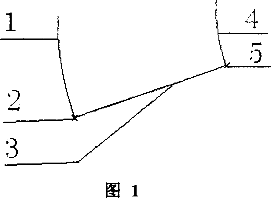
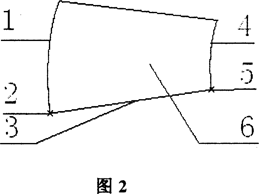
[0026] As shown in Figure 1-2, the big-endian theoretical involute 1, the big-endian theoretical involute starting point 2, the small-endian theoretical involute 4, the small-endian theoretical involute starting point 5, big-endian and small-endian The straight line formed by the starting points 2 and 5 in the same direction of the theoretical involute is the theoretical trajectory 3, any theoretical involute is used as the initial trajectory (Origin Trajectory), and the other theoretical involute is used as the control trajectory (X-Trajectory). Theoretical tooth surface 6 is obtained by variable section scanning method.

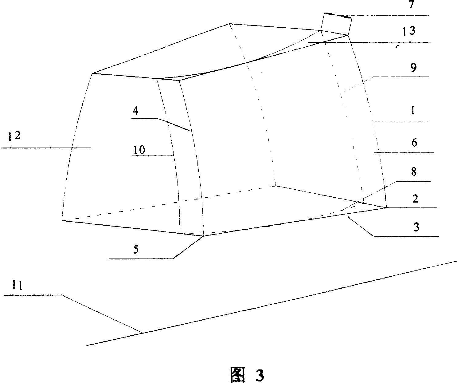
[0027] As shown in Figure 3, the tooth direction of any one of the conjugate gears is modified, and the tooth direction of the other gear in the conjugate gear is not modified; the two theoretical involutes of the tooth direction modified gear Respectively rotate around the gear central axis 11, the direction of rotation is biased toward the gear tooth enti...


PUM


Abstract

This invention discloses an involute gear shaping technique which includes the following processes: establish theoretic involute for the gear by CAD software; confirm the drum shaped size and maximum tooth profile; shape any one of the conjugate gears; shape the tooth profile of three-dimensional model of the above conjugate gears; convert the three-dimensional model to numeric control code and input to machine tool for machining. This invention simplifies traditional taper gear shaping technique. It reduces vibration & yawps in joggling and prevents edge effect.

Description

technical field [0001] The invention belongs to a gear manufacturing method, in particular to a method for modifying an involute spur bevel gear. Background technique [0002] The tooth surface of commonly used standard gears is a theoretical involute, and the actual meshing tooth surface deviates from the theoretical involute due to elastic deformation or local elastic deformation during meshing, resulting in vibration and noise; Errors cannot be avoided during installation, and it is difficult to ensure dimensional accuracy and installation accuracy, which will cause the meshing area of ​​the gear pair to not be in the middle of the tooth surface, and a pair of meshing gears with different tooth widths, resulting in edge effects and directly affecting the gear load. Increased capacity and service life. Through gear modification, the middle part of the tooth surface is modified into a convex shape, and the meshing area can be in the middle of the tooth surface. [0003] T...

Claims


Application Information

Patent Timeline
IPC IPC(8): G05B19/4097B23P6/00
Inventor 夏巨谌陈霞胡国安金俊松
Owner HUAZHONG UNIV OF SCI & TECH
Why Eureka
Try Eureka