Evolent straight-gear conic-gear direct-finishing method

A technology of bevel gears and involutes, applied in the field of gear manufacturing, can solve the problems of no parameterization, inaccuracy, and complicated modification methods, and achieve the effect of solving meshing contact

Inactive Publication Date: 2007-03-28
HUAZHONG UNIV OF SCI & TECH +1
View PDF3 Cites 30 Cited by
  • Summary
  • Abstract
  • Description
  • Claims
  • Application Information

AI Technical Summary

Problems solved by technology

Tooth profile modification is to modify the theoretical involute by means of spline fitting on the back cone plane of the bevel gear, instead of using the theoretical involute, which is suitable for straight bevel bevel gears with small modulus and small external dimensions. Inaccurate, and the modification method is complicated, and there is no parameterization

Method used


Image

  • Evolent straight-gear conic-gear direct-finishing method
  • Evolent straight-gear conic-gear direct-finishing method
  • Evolent straight-gear conic-gear direct-finishing method

Examples


Embodiment Construction

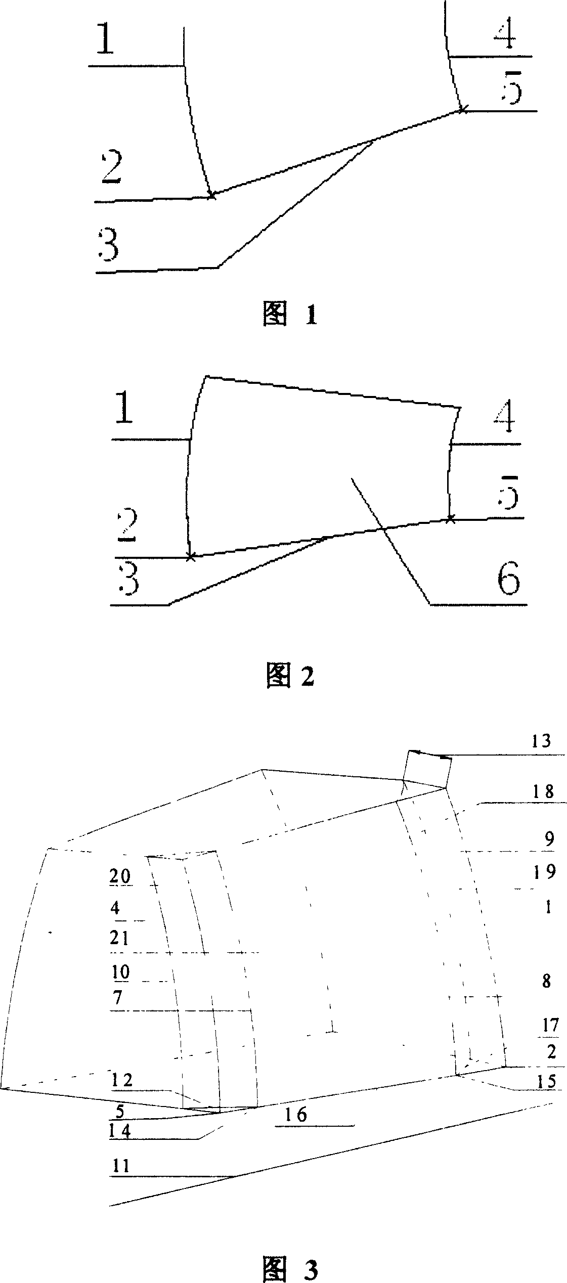
[0021] As shown in Figure 1-Figure 2, the involute of the big-endian theory is 1, the starting point of the involute of the big-endian theory is 2, the involute of the small-endian theory is 4, the starting point of the involute of the small-endian theory is 5, the big-endian and the small-endian The straight line formed by the starting points 2 and 5 in the same direction of the theoretical involute is the theoretical trajectory 3, any theoretical involute is used as the initial trajectory (Origin Trajectory), and the other theoretical involute is used as the control trajectory (X-Trajectory). Theoretical tooth surface 6 is obtained by variable section scanning method.

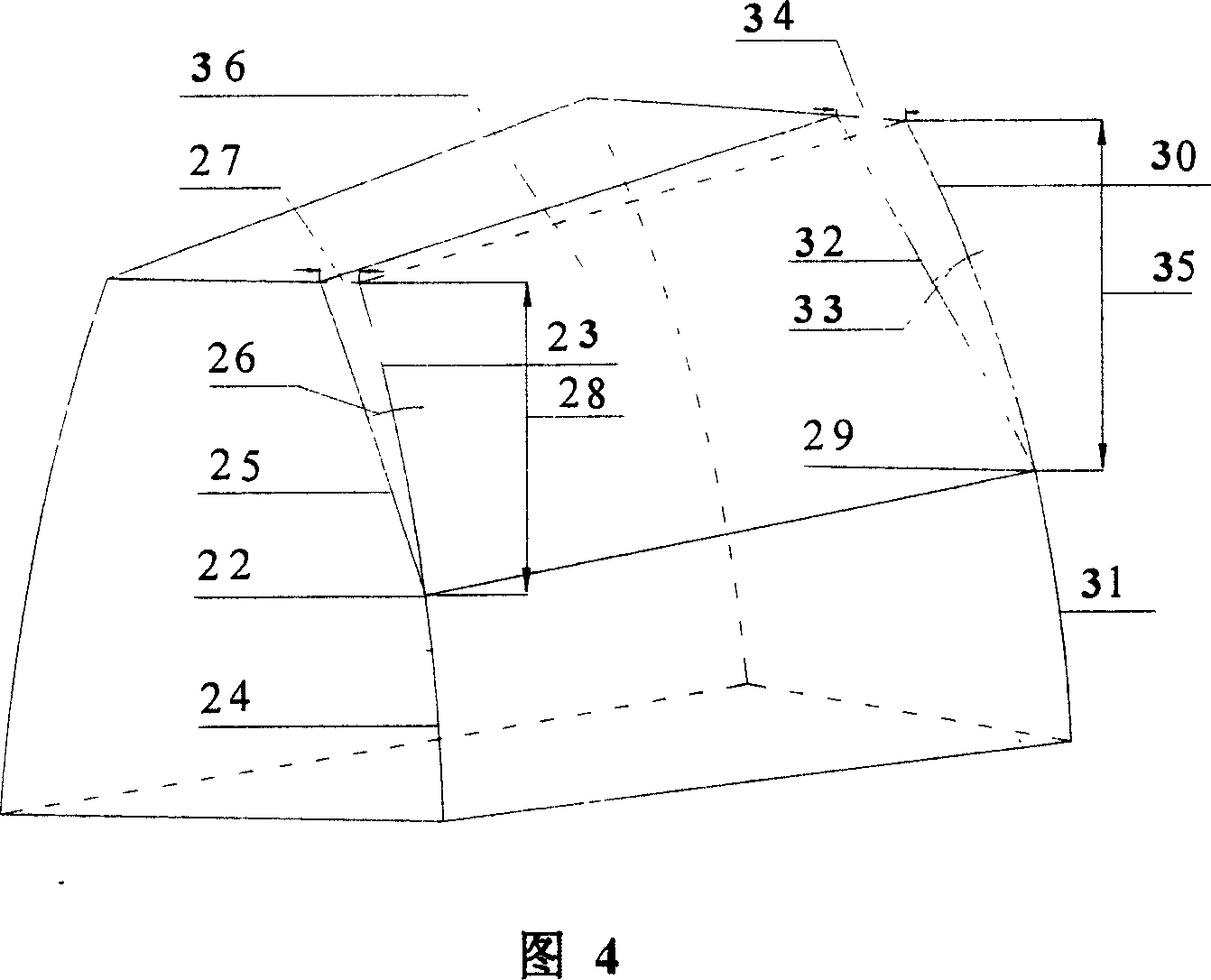
[0022] As shown in Figure 3, the tooth direction modification is performed on the theoretical trajectory of the gear; two theoretical involutes are established between the big-end theoretical involute 1 and the small-end theoretical involute 4: according to the small-end modification length Determine the theo...


PUM


Abstract

This invention is about the directly repair shape method, belongs to the manufacturing process of the gear wheel. This can make out the fixed-shape gear wheel straightly by numerical control machine, and no need to fix any more. The process is that: ensuring the fixed-magnitude, the max fix-length of the tooth profile and the longitudinal. It uses the three-dimensional shaping CAD software to build the four theoretical involutes. It has the tip relief by using conjugate gear three-dimensional model. It transforms the fixed-shape gear three-dimensional model into numerical code inputting, and then the numerical machine can directly fix the blank. This invention is easy to carry out, and can reduce the noise and shake, and at the same time it can reduce the edge-effect.

Description

technical field [0001] The invention belongs to a gear manufacturing method, in particular to a direct modification method of an involute spur bevel gear. Background technique [0002] The tooth surface of commonly used standard gears is a theoretical involute, and the actual meshing tooth surface deviates from the theoretical involute due to elastic deformation or local elastic deformation during meshing, resulting in vibration and noise; Errors cannot be avoided during installation, and it is difficult to ensure dimensional accuracy and installation accuracy, which will cause the meshing area of ​​the gear pair to not be in the middle of the tooth surface, and a pair of meshing gears with different tooth widths, resulting in edge effects and directly affecting the gear load. Increased capacity and service life. Through gear modification, the end of the tooth surface is repaired into an arc of equal radius, and the meshing area can be located in the middle of the tooth sur...

Claims


Application Information

Patent Timeline
Patent Type & Authority Applications(China)
IPC IPC(8): G05B19/4097B23P6/00
Inventor 夏巨谌陈霞胡国安金俊松
Owner HUAZHONG UNIV OF SCI & TECH
Why Eureka
Try Eureka