Non-field cage-shape tap changer for transformer

A technology of tap changer and transformer, which is applied in transformers, variable transformers, electric switches, etc., can solve the problems of low positioning accuracy of moving contacts, difficult contact shunting, affecting the performance of switches, etc., and achieves structural rigidity improvement, The effect of low production cost and small operating torque

Active Publication Date: 2007-03-21
WUHAN TAIPU TRANSFORMER CHANGER
View PDF0 Cites 6 Cited by
  • Summary
  • Abstract
  • Description
  • Claims
  • Application Information

AI Technical Summary

Problems solved by technology

When the existing cage switch is used as three-phase, the maximum current is generally 1200A. Due to factors such as the dispersion of manufacturing and the deformation of the insulating rod due to the tension of the lead wire, it is difficult to divide the current of each contact evenly when connected in parallel. Therefore, it is generally used when it is used as a single-phase switch. For 2500A to 3000A
However, when this structure is used to manufacture high-current switches, the biggest defect is that the rigidity of the cage is seriously insufficient, the volume is large, and when it is used for high voltage, the shielding is complicated everywhere, and the local field strength is too large, resulting in a large amount of partial discharge, and the structure is complex and the production cost is high.
In addition, due to the large radius of the moving contact, the sliding of the moving contact when the central axis rotates results in a large operating torque, and the positioning accuracy of the moving contact is low, often resulting in poor contact and affecting the performance of the switch
[0003] At present, with the increasing capacity of a single transformer, the current and voltage of the transformer are also increasing, so the requirements for switch specifications are also increasing. improve

Method used


Image

  • Non-field cage-shape tap changer for transformer
  • Non-field cage-shape tap changer for transformer
  • Non-field cage-shape tap changer for transformer

Examples


Embodiment Construction

[0017] Embodiments of the present invention will be further described below in conjunction with the accompanying drawings.

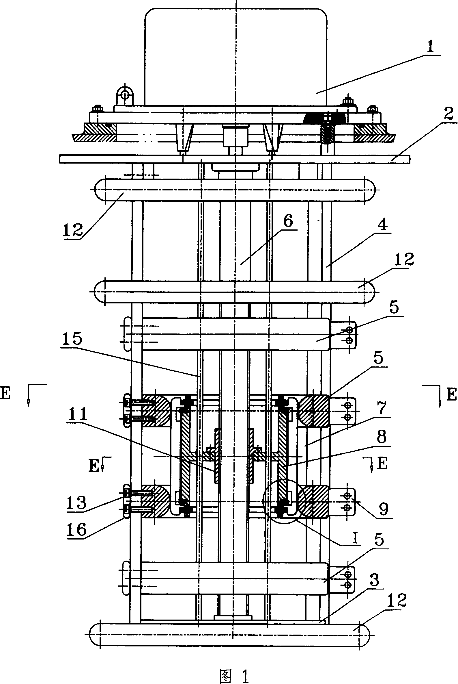
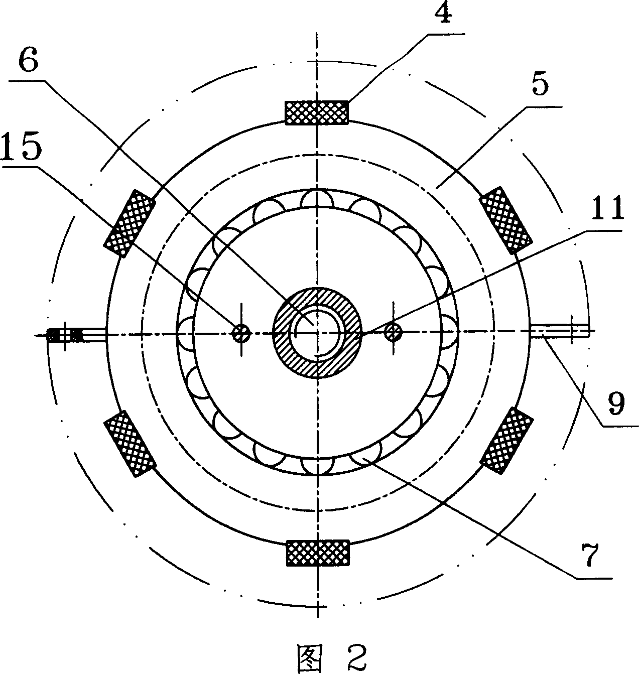
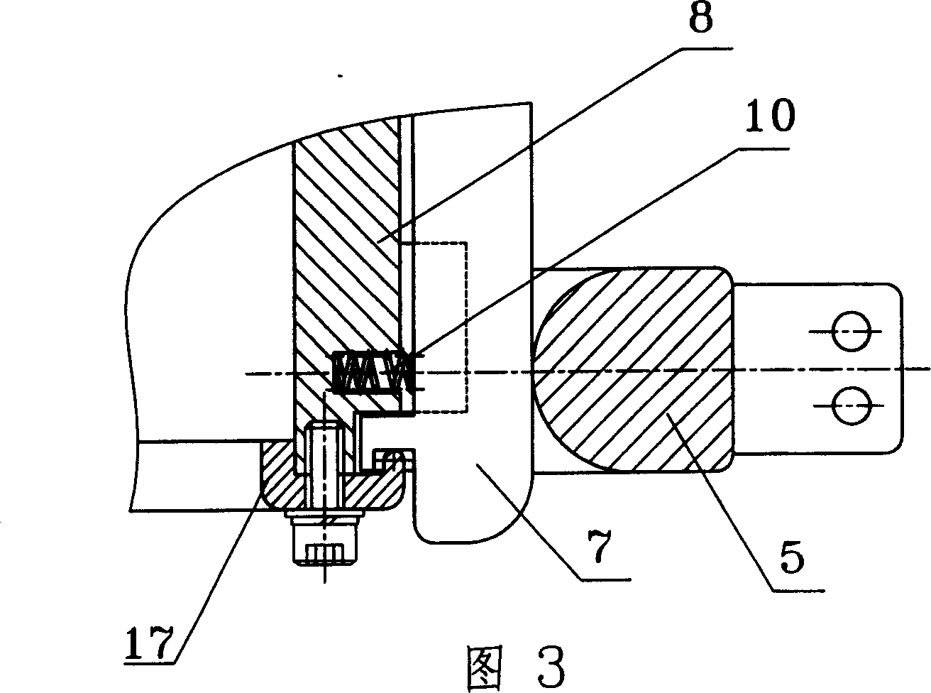
[0018] One embodiment of the present invention, as shown in Figures 1, 2, and 3, is a single-phase off-excitation cage tap changer with upper and lower supports 2, 3, and a transmission screw 6 is installed between the upper and lower supports. , the upper part of the transmission screw is connected with the operating mechanism 1, and the transmission screw is arranged with the screw sleeve 11 connected with the support to form a screw type upper and lower transmission device; 6 to 8 pieces are installed around the upper and lower supports. Insulating rods 4, ring-shaped static contacts 5 are arranged at intervals along the axial direction on the inside of the insulating rods, the ring-shaped static contacts are connected with each insulating rod through screws 13, and multiple ring-shaped static contacts can be arranged in the axial direction, usually 4 ...


PUM


Abstract

A cage-style tap-changer without excitation for transformer relates to up and down brackets and there are insulating pole of edge connecting between them. There are interval ring static state relays on the axes of insulating pole and there are dynamic relays at the up and down brackets and inside of the ring static state relays. The dynamic relays connects with one up/down gearing, and there are dynamic relays connects with closed two static state relays in the outside of dynamic relays subassembly and the corresponding ring static state relays. The beneficial effect is 1. The dynamic and static state relays touch with stabilization and short moment when switch operation moves along the axes and high orientation precision. 2. Static state relays enhance the stiffness of cage-style with strong anti-short ability of switch for large current and single-phase switch with high and insulated level.

Description

technical field [0001] The invention relates to a non-excitation cage tap changer for a transformer, which is a further improvement on the existing non-excitation cage tap changer. Background technique [0002] The existing non-excitation cage tap changer mainly includes upper and lower supports and insulating rods arranged at intervals along the circumferential direction of the upper and lower supports. Static contacts are arranged at intervals in the axial direction of each insulating rod, and the static contacts on each insulating rod The heads correspond to form a circumferential static contact group, and a central axis is installed between the upper and lower supports. The central axis corresponds to the static contact and sets the moving contact between the two adjacent static contacts through the support. When the shaft is rotated and positioned, the movable contact rotates in the circumferential plane and bridges with different static contact groups respectively to r...

Claims


Application Information

Patent Timeline
Patent Type & Authority Applications(China)
IPC IPC(8): H01F29/04H01H3/40H01H1/56
CPCH01H2009/0022H01H9/0016H01F29/02
Inventor 秦伟
Owner WUHAN TAIPU TRANSFORMER CHANGER
Why Eureka
Try Eureka