Controllable gap for protecting transformer neutral point

A transformer neutral point and gap technology, applied in the direction of emergency protection circuit devices, electrical components, etc., can solve the problems of electrode ablation, inaccurate distance adjustment, and harsh coordination requirements, so as to eliminate the influence of stray capacitance and determine the distance Accurate, satisfying effect of correctness

Active Publication Date: 2007-03-21
CHINA ELECTRIC POWER RES INST +2
View PDF1 Cites 14 Cited by
  • Summary
  • Abstract
  • Description
  • Claims
  • Application Information

AI Technical Summary

Problems solved by technology

Single gap protection has the defects of inaccurate distance adjustment, poor concentricity, and discharge voltage change caused by electrode ablation after discharge, and the problem that the chopping wave generated after the gap breaks down under lightning overvoltage is relatively harmful to the neutral point insulation of the transformer. ;Single arrester protection In the case of a single-phase grounding and ground loss fault or non-full-phase operation of the system, the arrester is prone to damage or explosion; the gap and arrester are connected in parallel protection, due to the difference between the protection level of the arrester, the action characteristics of the rod gap and the insulation level of the transformer neutral point The coordination requirements between them are very strict, and it is difficult to realize
[0003] The transformer neutral point protection compound claw gap (utility model patent number ZL 200520000584.9) jointly developed by Xiaoguo Electric Power Research Institute, North China Electric Power University and Shandong Taiguang Electric Appliance Co., Ltd. effectively solves the problem of inaccurate distance adjustment and concentricity in the rod gap. However, the problem of wave clipping caused by breakdown under lightning impact and the insulation coordination with lightning arresters are still unsolved.

Method used


Image

  • Controllable gap for protecting transformer neutral point
  • Controllable gap for protecting transformer neutral point

Examples


Embodiment Construction

[0015] The present invention will be further described below in conjunction with the accompanying drawings and embodiments.

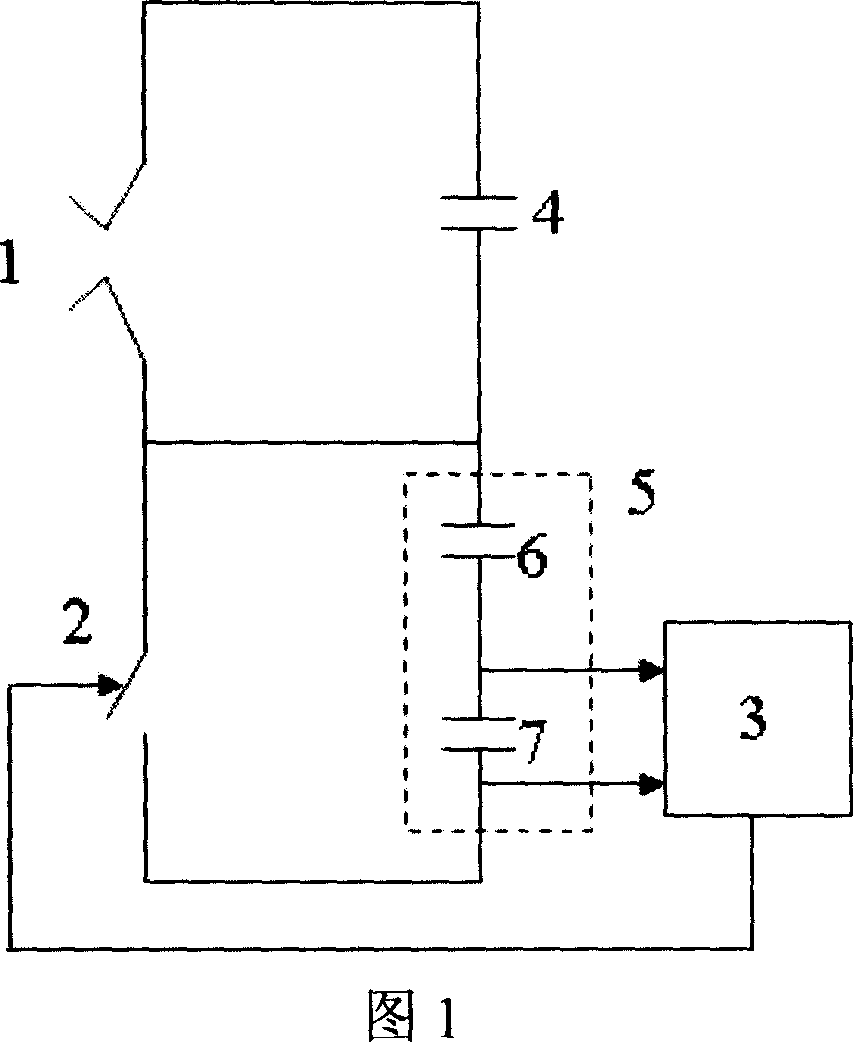
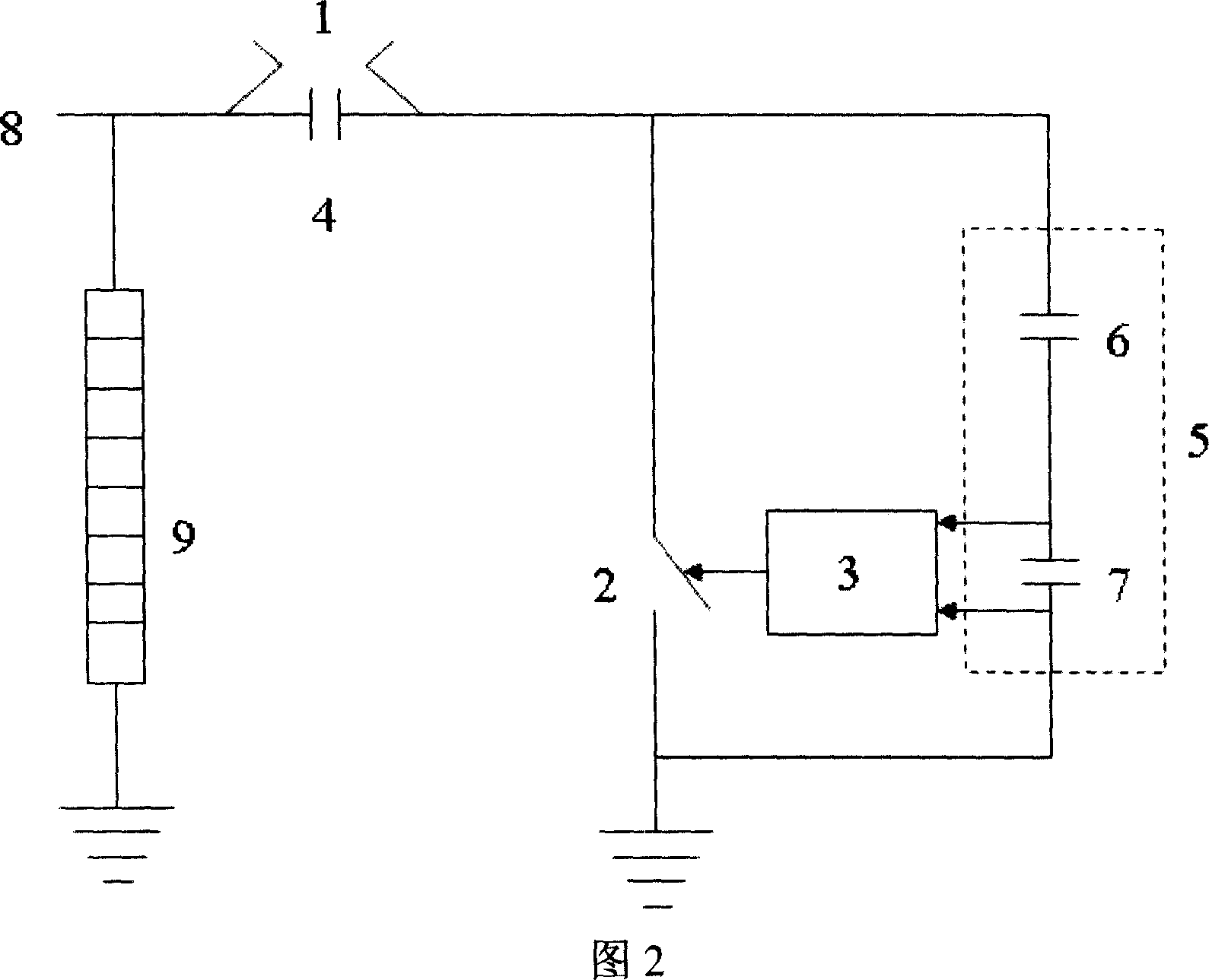
[0016] Referring to FIG. 1 , a controllable gap for protecting the neutral point of a transformer includes a fixed gap 1 , a control gap 2 and its control loop 3 , and a capacitive voltage equalizing circuit composed of voltage equalizing capacitors 4 and 5 . Figure 1 shows that the fixed gap 1 is connected in series with the control gap 2, and the control gap 2 is electrically connected with the control circuit 3 to be controlled by it. The voltage equalizing capacitor 5 is a voltage divider formed by connecting capacitors 6 and 7 in series. The upper arm capacitor 6 has a small capacitance and a high withstand voltage, and is also called a voltage equalizing capacitor; the capacitance of the lower arm capacitor 7 is hundreds of capacitors 6 , Thousand times, to provide an input signal to the control loop 3, also known as the measurement capacitance. ...


PUM


Abstract

This invention relates to a control gap used in protecting neutral points of transformers including a fixed gap, a control gap and its control loop and a capacitance equalizing loop, in which, the fixed gap is serial to the control gap, one end of the fixed gap is connected to the neutral point and one end of the control gap is connected to the earth, the control gap is controlled by the control loop to trigger actions, the capacitance equalizing loop is parallel at both ends of the fixed gap and control gap for bleeding, the equalizing capacitor parallel to the control gap is composed of a serial equalizing capacitor with small capacitance value and high voltage endurance and a measuring capacitor with great capacitance and low voltage endurance providing input signals for the control loop. This invention jointly uses an arrester often used for transformer neutral point to protect the neutral point including: impacted by thunder and operation, the arrester operates to limit over voltage of the neutral point, when the point insulated line-frequency over voltage is threatened in the system, the control gap breaks through it to discharge to protect the insulation of the point and the arrester.

Description

technical field [0001] The invention relates to the overvoltage protection of the power system, especially the overvoltage protection for the neutral point of the transformer. Background technique [0002] At present, the commonly used protection methods for the neutral point of domestic 110kV and 220kV transformers are: single gap protection, single arrester protection and gap and arrester parallel protection, all of which have inherent defects. Single gap protection has the defects of inaccurate distance adjustment, poor concentricity, and discharge voltage change caused by electrode ablation after discharge, and the problem that the chopping wave generated after the gap breaks down under lightning overvoltage is relatively harmful to the neutral point insulation of the transformer. ;Single arrester protection In the case of a single-phase grounding and ground loss fault or non-full-phase operation of the system, the arrester is prone to damage or explosion; the gap and ar...

Claims


Application Information

Patent Timeline
Patent Type & Authority Applications(China)
IPC IPC(8): H02H7/04
Inventor 陈维江林耀洲颜湘莲
Owner CHINA ELECTRIC POWER RES INST
Why Eureka
Try Eureka