Jointing pant of automobile drive system

A technology for connecting parts and transmission systems, applied in the field of connecting parts, to achieve the effect of increasing service life, reducing diameter and thickness, and widening the selection range

Inactive Publication Date: 2010-05-12
SHIYAN YIXING IND DEV
View PDF4 Cites 0 Cited by
  • Summary
  • Abstract
  • Description
  • Claims
  • Application Information

AI Technical Summary

Problems solved by technology

Due to the limitation of this connection structure, the material of the connection parts can only be selected from alloy structural steel

Method used


Image

  • Jointing pant of automobile drive system
  • Jointing pant of automobile drive system
  • Jointing pant of automobile drive system

Examples


Embodiment Construction

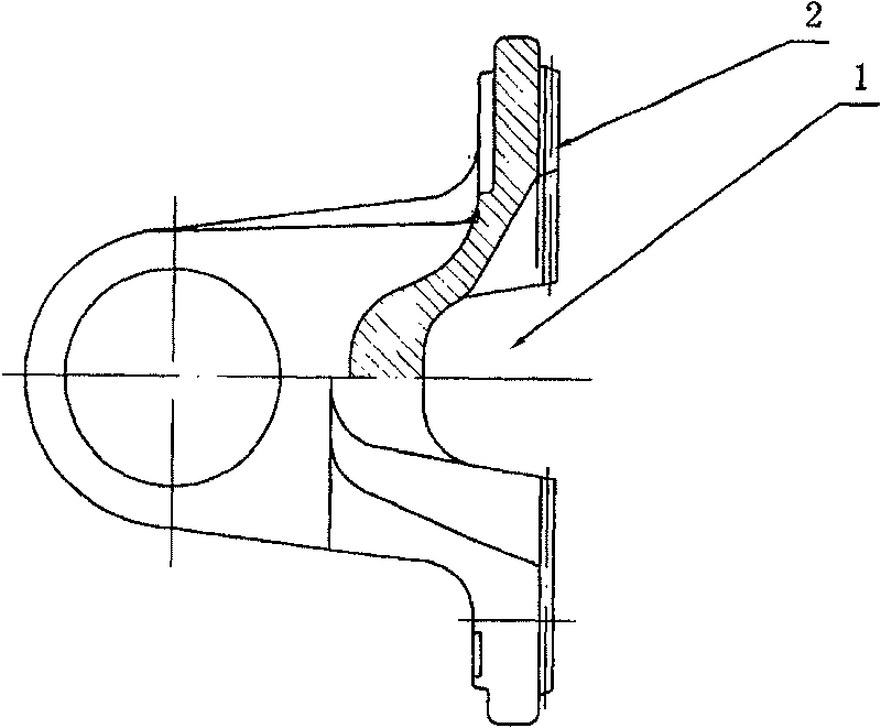
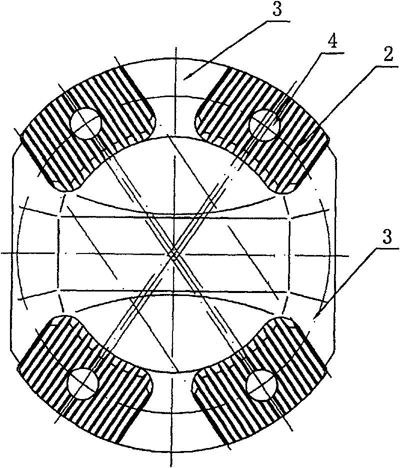
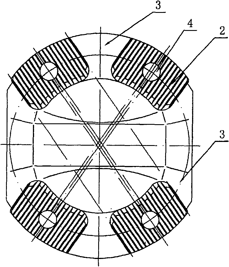
[0009] Such as figure 1 , 2 The structure of the connecting part of the end face of the connecting parts of the automobile transmission system shown is: the central part 1 of the end face is recessed, two sets of end face teeth 2 distributed at a certain angle are arranged on the end face circumference, and the end face circumference parts avoiding the end face teeth 2 are set. There is a sunken weight-reducing groove 3; a connecting hole 4 is also provided on the circumference of the end face.

[0010] The angle between the two groups of face teeth is generally between 60° and 80°, and the number of teeth in each group of face teeth is 6 to 10. The tooth shape of the end tooth is generally rectangular or involute or trapezoidal, and it is most convenient to process with rectangular teeth.

[0011] Combined with the structure and space arrangement of the connecting parts of the current automobile transmission system, the angle between the two sets of end face teeth is prefer...


PUM


Abstract

This invention puts forward connecting parts for improving the structure of an end face connecting part, in which, the structure of the end-face connection part includes: the central part of the end face is sunken, two groups of end face teeth distributed in a certain angle are set on the circle of the end face, a sunk weight-reduction groove is set at the end face circle avoiding the end-face teeth, besides, a connection hole is set on the circle of the end-face, which solves the cut and loss of drive parts at work by applying the structure of the end face teeth, two sets of end-face teeth are crossed, the self-centering of the parts is ensured and the moment transmission of cars is stable in running and the life time of parts is increased.

Description

technical field [0001] The invention relates to connecting parts of automobile transmission system. Background technique [0002] In the automotive transmission system, the connecting parts of the connecting parts are constantly subjected to shear and tensile impacts, and once they fail, it will cause safety accidents. At present, the connection parts of the connecting parts of the domestic heavy-duty vehicle transmission system are all flange structures, the end faces are matched with bolts, and the torque is transmitted by the friction between the two ends and the bolts during work. The bolts carry a large torque during the work process. Under the impact of continuous shearing and stretching, it is easy to cause bolt shearing and cause failure. In order to ensure sufficient strength of the bolts, in the design, the volume of the parts should be increased as much as possible, and the number of bolts should be increased, which will bring about an increase in various economi...

Claims


Application Information

Patent Timeline
Patent Type & Authority Patents(China)
IPC IPC(8): F16D1/112
Inventor 曹立新
Owner SHIYAN YIXING IND DEV
Why Eureka
Try Eureka