
Current-controlled cmos delay cell with variable bandwidth

A current control and broadband technology, applied in the field of delay cells, can solve the problems of high energy consumption of delay blocks

Inactive Publication Date: 2007-03-28
BROADCOM CORP
View PDF4 Cites 4 Cited by
  • Summary
  • Abstract
  • Description
  • Claims
  • Application Information

AI Technical Summary

Problems solved by technology

In the previous technology process, each independent delay block will bring higher energy consumption

Method used


Image

  • Current-controlled cmos delay cell with variable bandwidth
  • Current-controlled cmos delay cell with variable bandwidth
  • Current-controlled cmos delay cell with variable bandwidth

Examples


Embodiment 400

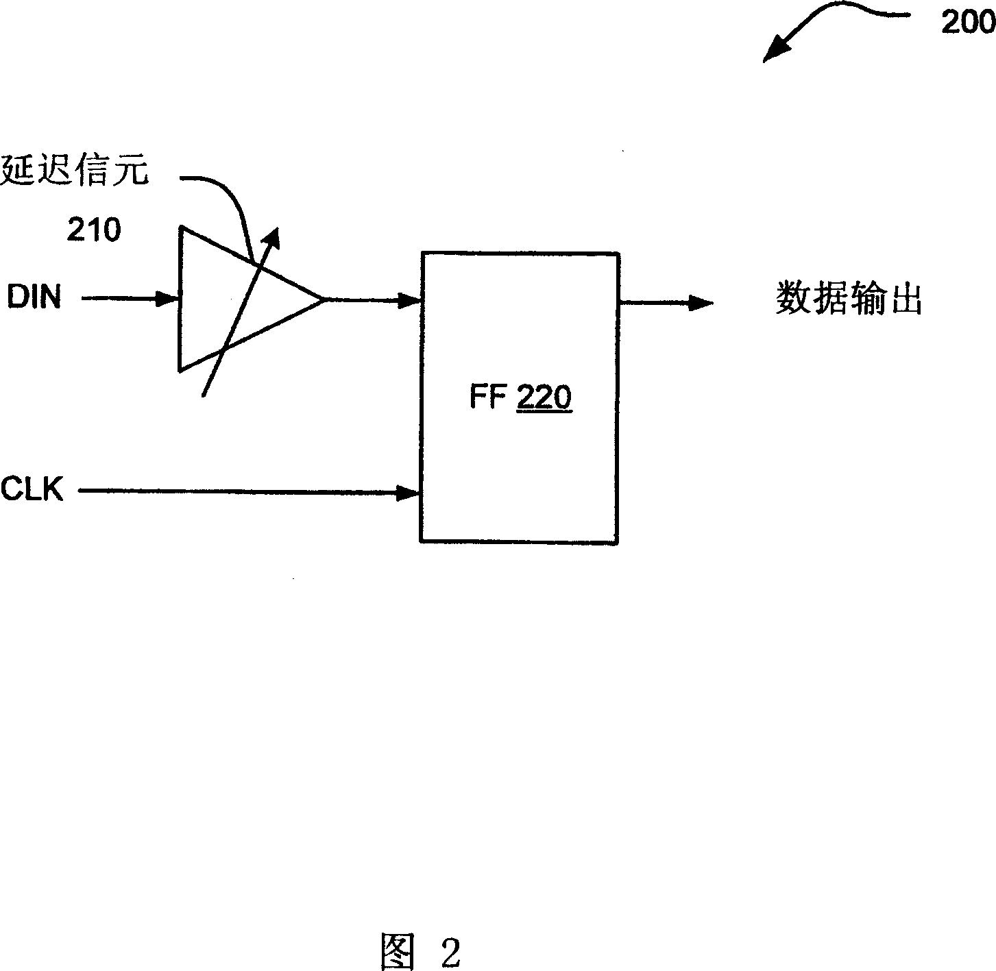
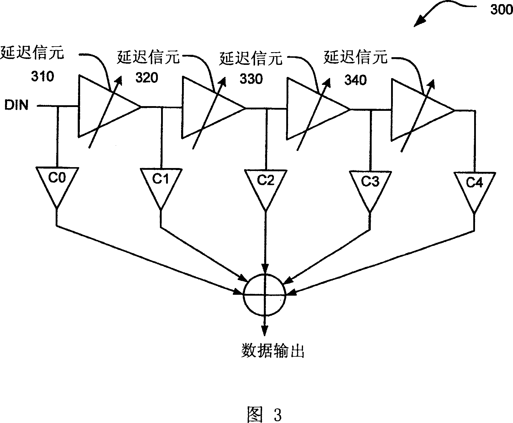
[0113] Embodiment 400 mixes two types of buffers: slow buffers and fast buffers. In a particular application, greater latency is required or required, which necessarily results in lower bandwidth in embodiment 400 . In such an example, the low bandwidth is equivalent to a low-pass filter (LPF). Such an LPF filter may cause undesired corruption of the signal due to low frequency truncation. Unwanted intersymbol interference (ISI) may also arise due to this LPF low-pass filtering. In very high-speed broadband applications, this effect can significantly degrade overall performance.

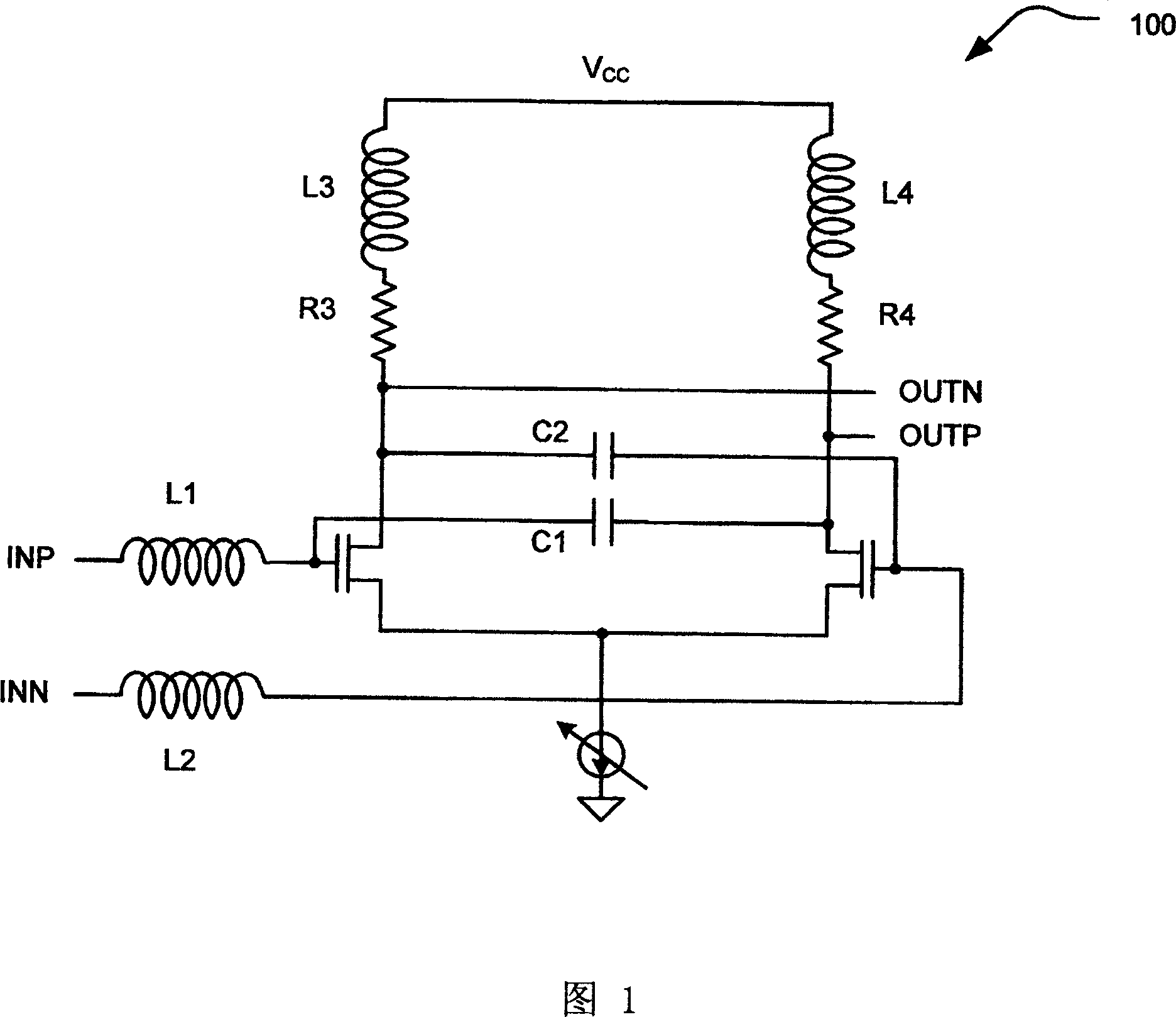
[0114] Figure 5 shows an embodiment 500 of a wideband variable delay cell. In this embodiment 500, the signal input is connected to an extended bandwidth current controlled CMOS (C3MOS) wideband data amplifier circuit similar to the embodiment 100 of FIG. 1 . The operation of this enlarged bandwidth broadband data amplifier circuit, U.S. Patent Application No. 10 / 028,806, now U.S. Patent No. 6,62...


PUM


Abstract

Current-controlled CMOS (C3MOS) fully differential integrated delay cell with variable delay and high bandwidth. A novel implementation includes a wideband differential transistor pair and a cross-coupled differential transistor pair. The wideband differential transistor pair can be implemented with appropriate input and output impedances to extend its bandwidth for use in broadband applications. These two stages, (1) buffer stage (or data amplifier stage) and (2) cross-coupled differential pair stage, are both very fast operating stages. This design does not incur any increased loading to previous or subsequent stages in a device. In addition, there is no increase in the total amount of current that is required.

Description

technical field [0001] The present invention relates to the field of communication equipment, and more specifically, relates to a delayed cell implemented in the communication equipment. Background technique [0002] Data communication systems have undergone continuous development over the years. In many broadband data communication system applications, variable delay cells are used. In these applications, however, it is often required to adjust the timing control between the different components. One such application of delay cells is in a delay locked loop (DLL). A common way to design a DLL is to use many delay blocks. In the previous technology, each independent delay block will bring high energy consumption. Designing a more energy-efficient delay block is worth looking forward to. [0003] Proper positioning and control of the different elements within a communication system often require safeguards by which the various signals are conditioned to ensure proper pos...

Claims


Application Information

Patent Timeline
IPC IPC(8): H03F1/48
Inventor 曹军
Owner BROADCOM CORP
Learn More