Casting trough and method for casting copper anodes

A pouring trough and casting mold technology, applied to casting equipment, control of molten metal pouring from casting ladles, casting molten material containers, etc., can solve problems such as bottlenecks and slowness of casting steps, and achieve reduced fluctuations, reduced wear, and reduced fluctuating effect

Inactive Publication Date: 2007-03-28
OUTOTEC OYJ
View PDF1 Cites 20 Cited by
  • Summary
  • Abstract
  • Description
  • Claims
  • Application Information

AI Technical Summary

Problems solved by technology

However, this slow pouring causes the casting step to become the bottleneck of the entire process

Method used


Image

  • Casting trough and method for casting copper anodes
  • Casting trough and method for casting copper anodes
  • Casting trough and method for casting copper anodes

Examples


Embodiment Construction

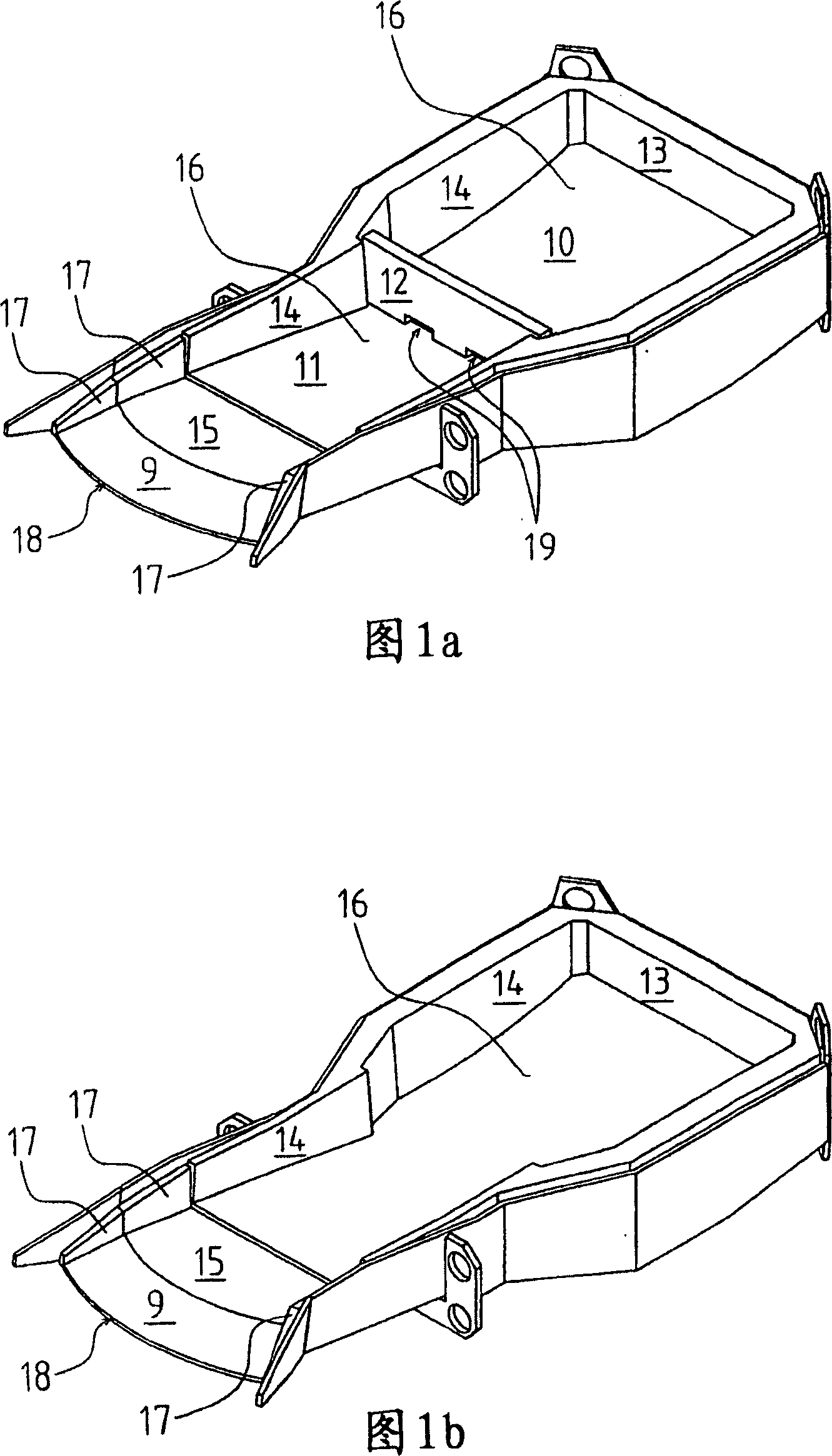
[0033] The pouring trough according to FIG. 1 a has a curved bottom 16 , side walls 14 and a rear wall 13 . A choke brick 12 is placed between the outlet, in this case the outlet brick 15 , and the rear wall 13 . The choke brick 12 divides the space defined by the bottom and the walls into the front part 11 of the pouring trough and the rear end 10 of the pouring trough. Notches made at the bottom edge of the choke block 12 and the bottom 16 of the pouring trough define a gap 19 through which molten metal flows from the rear end 10 of the pouring trough to the front part 11 . The height of the choke element is preferably chosen such that it extends from the bottom of the pouring trough at least to the level of the surface of the melt when the pouring trough is in the filling position. When feeding molten metal in the pouring trough, this metal is divided between the front part 11 and the rear end 10 of the pouring trough. It is preferable to supply molten metal into the spac...


PUM

PropertyMeasurementUnit
thicknessaaaaaaaaaa
heightaaaaaaaaaa
widthaaaaaaaaaa

Abstract

The invention is a casting trough and method for pouring molten metal in a casting mold. Owing to the design and trajectory of the casting trough, there is achieved an even and rapid pouring from the casting trough to the casting mold. The spout of the casting trough comprises a curved pouring edge and a downwardly directed curved pouring surface. The mass flow rate of the molten metal is controlled by means of a choke element fitted in the casting trough. The direction and magnitude of the kinetic energy of the molten metal are affected by the design of the spout of the casting trough and by a suitably chosen trajectory of the pouring motion.

Description

technical field [0001] This invention relates to a method and apparatus for pouring molten material, such as molten metal, into a casting mold. More precisely, the present invention relates to methods and apparatus for cast anodes used in electrorefining. Background technique [0002] Controlled pouring and precise feeding of the casting mold is important, for example, in the casting of metal anodes, in the production of which the subsequent processing step after metal anode casting is electrolytic refining, wherein in order to achieve high cathode quality and A prerequisite for high efficiency, among other requirements, is a uniform mass with respect to shape and weight. In most known methods, the anode is cast in an open mold. [0003] During the casting of anodes, such as copper anodes, the melt is guided from the anode furnace, for example along an inclined chute, to an intermediate channel of the casting plant, from where the molten metal is poured on to the pouring t...

Claims


Application Information

Patent Timeline
Patent Type & Authority Applications(China)
IPC IPC(8): B22D35/04B22D37/00B22D39/04B22D41/04B22D
CPCB22D41/04B22D35/04B22D37/00
Inventor J·伦皮奥
Owner OUTOTEC OYJ
Why Eureka
Try Eureka