Floor processing machine

A floor and grinding machine technology, applied in the field of processing or grinding machines, can solve problems such as the power problem of mobile grinding machines, and achieve the effect of excellent maneuverability

Inactive Publication Date: 2007-03-28
HTC SWEDEN AB
View PDF6 Cites 6 Cited by
  • Summary
  • Abstract
  • Description
  • Claims
  • Application Information

AI Technical Summary

Problems solved by technology

Again, this mobile grinder suffers from power issues

Method used


Image

  • Floor processing machine
  • Floor processing machine
  • Floor processing machine

Examples


Embodiment Construction

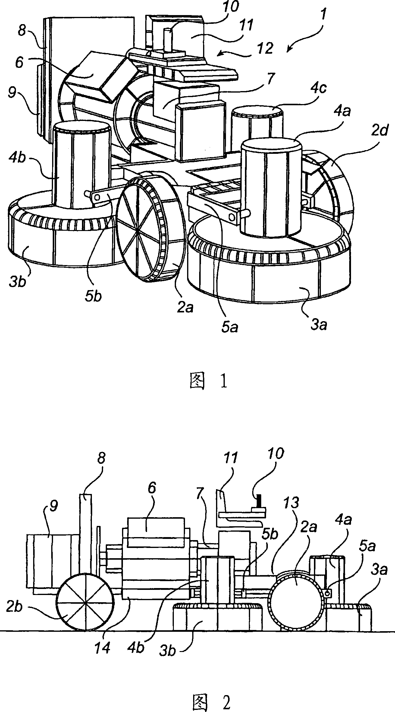
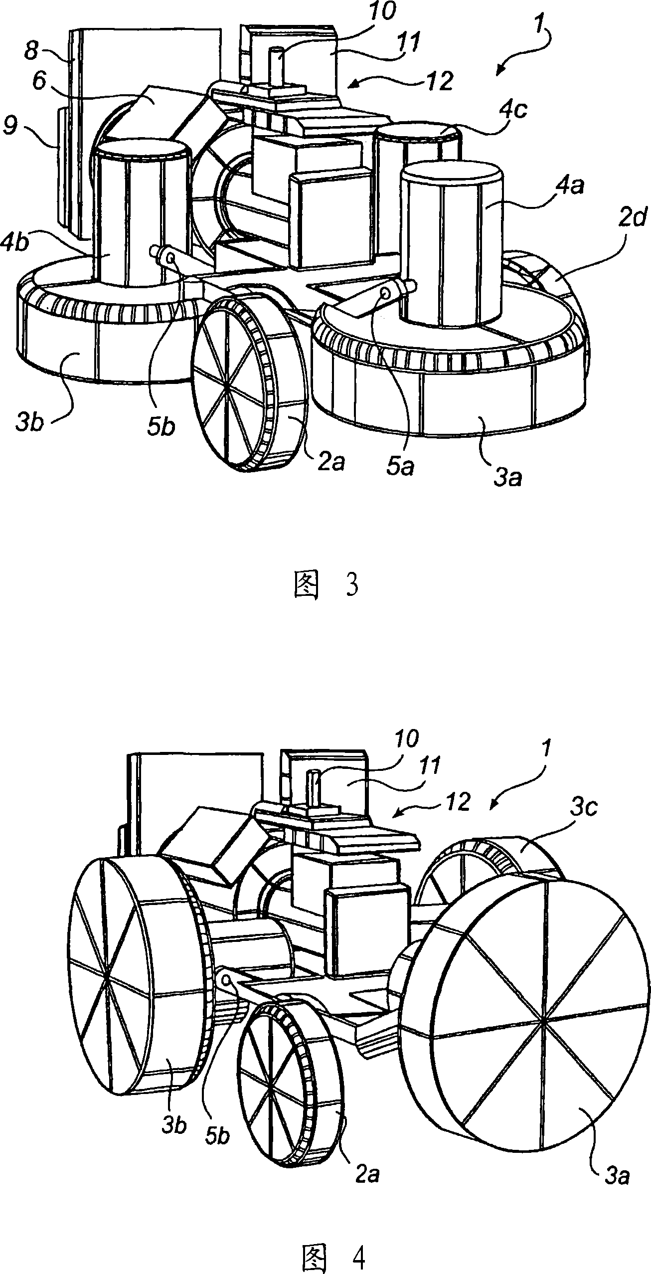
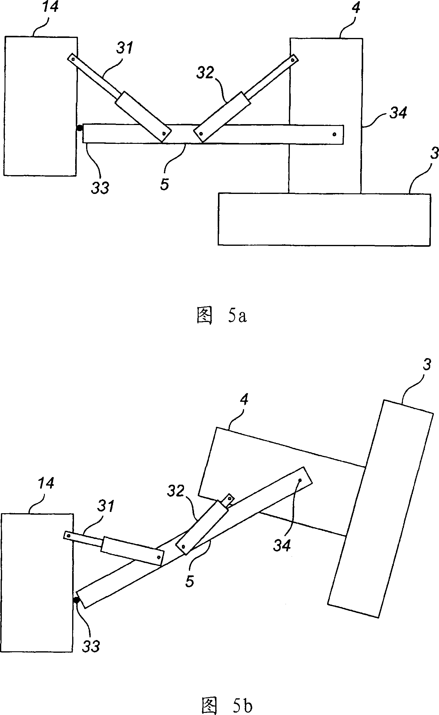
[0040] Figure 1 shows a ride-on grinder 1 comprising a frame 14 (Figure 2) on which a set of wheels 2a, 2b, 2c and 2d are arranged so that the grinder can be moved on a base 20 (Figure 2) .

[0041] The frame 14 of the grinder is arranged to support substantially all parts of the grinder. The frame may be a substantially rigid frame member or floor, or hinged, for example for handling purposes.

[0042] Said set of wheels 2a, 2b, 2c and 2d is used to provide a two-dimensional support surface for the grinder 1 on the base body 20 and can be designed in different forms, depending on the required drive characteristics of the grinder.

[0043] The frame also supports the engine 6 . The size and forcing / fuel of the engine are determined based on the power required by the grinder. In one embodiment of the grinder 1, the engine may be a gasoline or diesel internal combustion engine. The engine 6 is properly arranged to operate at a substantially constant speed and load, thus redu...


PUM


Abstract

A finishing machine (1) for finishing a work surface (20) which consists of a floor of terrazzo, marble, stone, concrete or the like, comprises at least two finishing units (3a, 4a; 3b, 4b; 3c, 4c, 300) which are supported by the frame (14, 100) of the finishing machine and which are arranged for grinding, polishing and / or machining of the work surface (20), and each machining unit comprises a motor (4a, 4b, 4c, 200) and a rotatably mounted working disc (41) driven by the motor. The finishing units (3a, 4a; 3b, 4b; 3c, 4c, 300) are individually tiltable relative to the frame (14, 100) about respective axes that are substantially parallel to the work surface (20).

Description

technical field [0001] The invention relates to a processing or grinding machine for grinding, polishing and / or cutting processing of hard floors such as terrazzo, marble, rock, concrete floors or the like according to the preamble of claim 1 . Background technique [0002] Machines for grinding hard floors such as terrazzo, marble, rock, concrete slabs or the like are well known and sold in particular by the applicant. Grinding machines used for this purpose in the prior art generally comprise a rotatably mounted sun disc, driven by an electric motor and on which are arranged a number of planetary discs, usually 3-6. One or more grinding members, polishing members and / or cutting tools are arranged on each planetary disc. Said grinding machine generally has an operating handle, adjacent to which drive means are located; wheels, constituting the support and facilitating the operation of said grinding machine, and optionally allowing a water tank for supplying water to the gr...

Claims


Application Information

Patent Timeline
IPC IPC(8): B24B7/18B24B
Inventor 哈坎·瑟塞尔
Owner HTC SWEDEN AB
Why Eureka
Try Eureka