Standing wave particle beam accelerator

An accelerator and particle beam technology, applied in the field of standing wave particle beam accelerators

Active Publication Date: 2007-03-28
VARIAN MEDICAL SYSTEMS
View PDF9 Cites 9 Cited by
  • Summary
  • Abstract
  • Description
  • Claims
  • Application Information

AI Technical Summary

Problems solved by technology

Thus, if the hospital changes its energy beam requirements, it will have to form a different accelerator

Method used


Image

  • Standing wave particle beam accelerator
  • Standing wave particle beam accelerator
  • Standing wave particle beam accelerator

Examples


Embodiment Construction

[0020] In the following, different embodiments of the present invention are described with reference to the accompanying drawings. It should be noted that the drawings are not drawn to scale and that elements of similar structure or function are denoted by the same reference numerals throughout. It should also be noted that these drawings are only intended to facilitate the description of specific embodiments of the invention, and are not intended to be an exhaustive description of the invention or to limit the scope of the invention. Furthermore, the illustrated embodiments do not necessarily have all of the illustrated aspects or advantages of the invention. Even if not shown as such, an aspect or advantage described in connection with a particular embodiment of the invention is not necessarily limited to that embodiment, but can be achieved in any other embodiment of the invention.

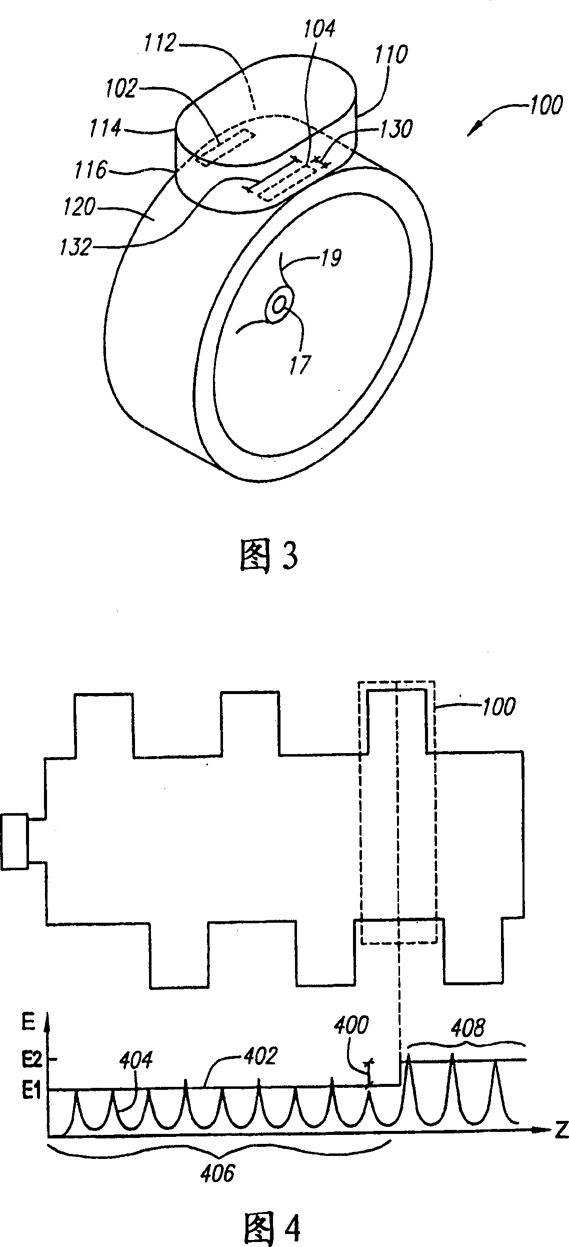
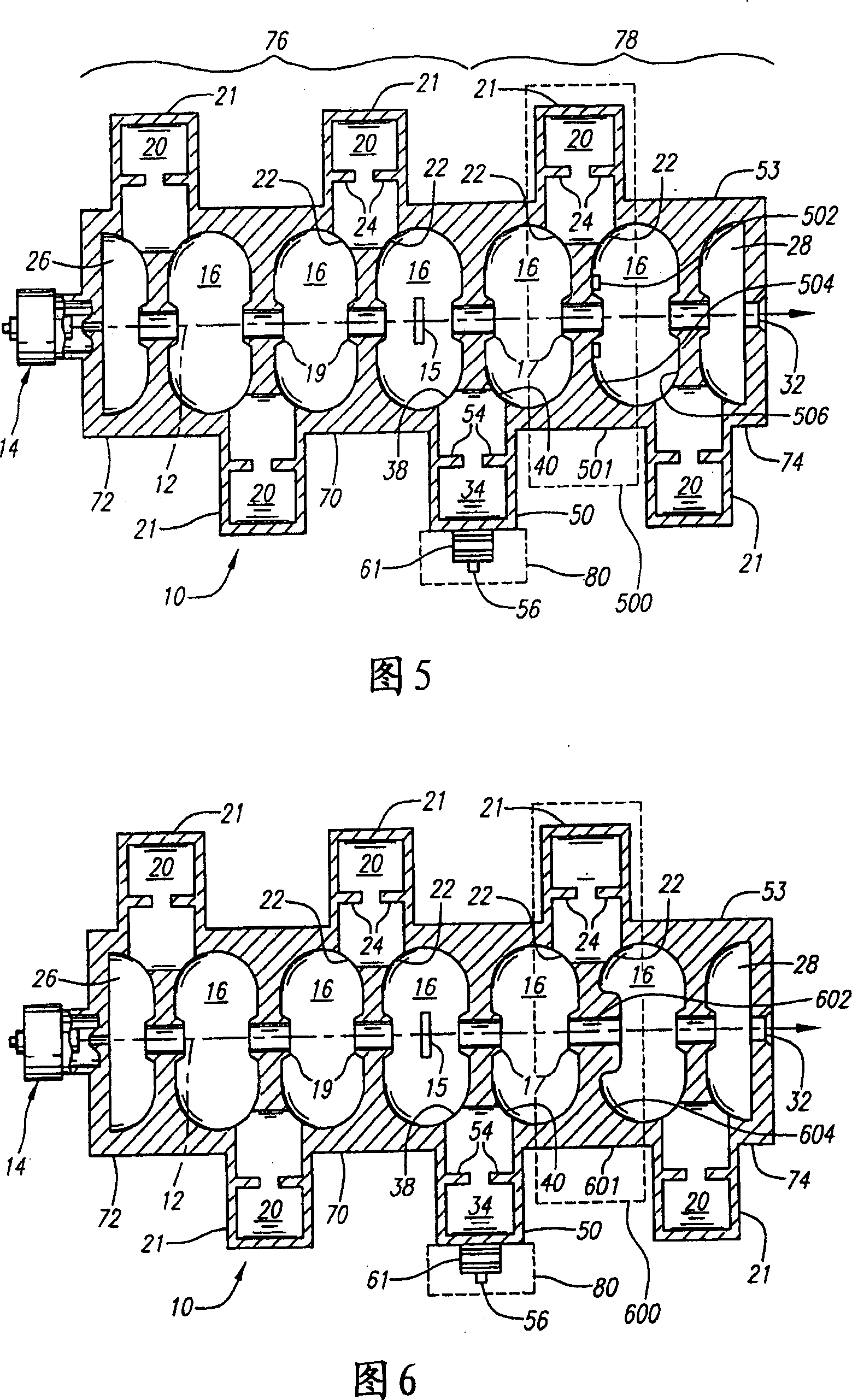
[0021] 1 is a schematic axial cross-sectional view of a charged particle standing wave acc...


PUM


Abstract

An accelerator for accelerating a particle beam includes a main body having a plurality of electromagnetic cavities coupled in series, and a first coupling body having a first side cavity coupled to one of the electromagnetic cavities through a first opening, and to another of the electromagnetic cavities through a second opening, wherein the first opening and the second opening have different configurations. The accelerator further includes a pair of conductive capacitively coupled noses secured to side walls of the first coupling body, wherein the pair of noses have equal lengths.

Description

technical field [0001] This invention relates generally to standing wave particle beam accelerators and, more particularly, to an electron accelerator for generating x-rays and beams of different energies. Background technique [0002] Standing wave particle beam accelerators have found widespread use in medical accelerators, where high energy particle beams are used to generate X-rays. In this application, the beam energy and output dose-rate must be stable. It would also be desirable to conveniently and reliably switch the energy of particle beams during medical treatment to provide treatment beams of different energies to achieve dose depth penetration. [0003] Different techniques for controlling the beam energy have been employed. In US Patent No. 4,286,192 to Tanabe and Vaguine, energy is controlled by decelerating the beam by reversing the accelerating field within a portion of the accelerator. In US Patent No. 4,382,208 to Meddaugh et al., the electromagnetic fie...

Claims


Application Information

Patent Timeline
Patent Type & Authority Applications(China)
IPC IPC(8): H01J25/10H05H9/04
CPCH05H9/04H05H9/044H05H9/048
Inventor G·E·梅德奥格M·E·特雷尔D·惠特姆
Owner VARIAN MEDICAL SYSTEMS
Why Eureka
Try Eureka