
Electric spanner with variable torsional moment

An electric wrench, power shaft technology, applied in the direction of wrenches, power tools, wrenches, etc., can solve the problems of shortening the service life of the motor, burning the vehicle fuse, etc.

Inactive Publication Date: 2007-04-04
ZHEJIANG JINZI MACHINERY&ELECTRICAL
View PDF0 Cites 1 Cited by
  • Summary
  • Abstract
  • Description
  • Claims
  • Application Information

AI Technical Summary

Problems solved by technology

[0003] At present, the existing electric wrench on the market is in the process of starting and accelerating, which is overloaded and working with super large current, which will cause the fuse of the vehicle to burn out and shorten the service life of the motor. It is necessary to have a method that does not overload and does not generate super large current during the process of starting and accelerating. buffer device

Method used


Image

  • Electric spanner with variable torsional moment
  • Electric spanner with variable torsional moment
  • Electric spanner with variable torsional moment

Examples


Embodiment Construction

[0017] Below in conjunction with accompanying drawing 1 to accompanying drawing 5 illustrate embodiment of the present invention:

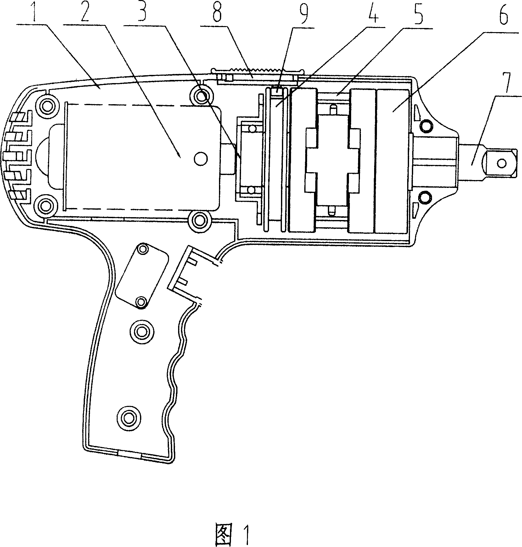
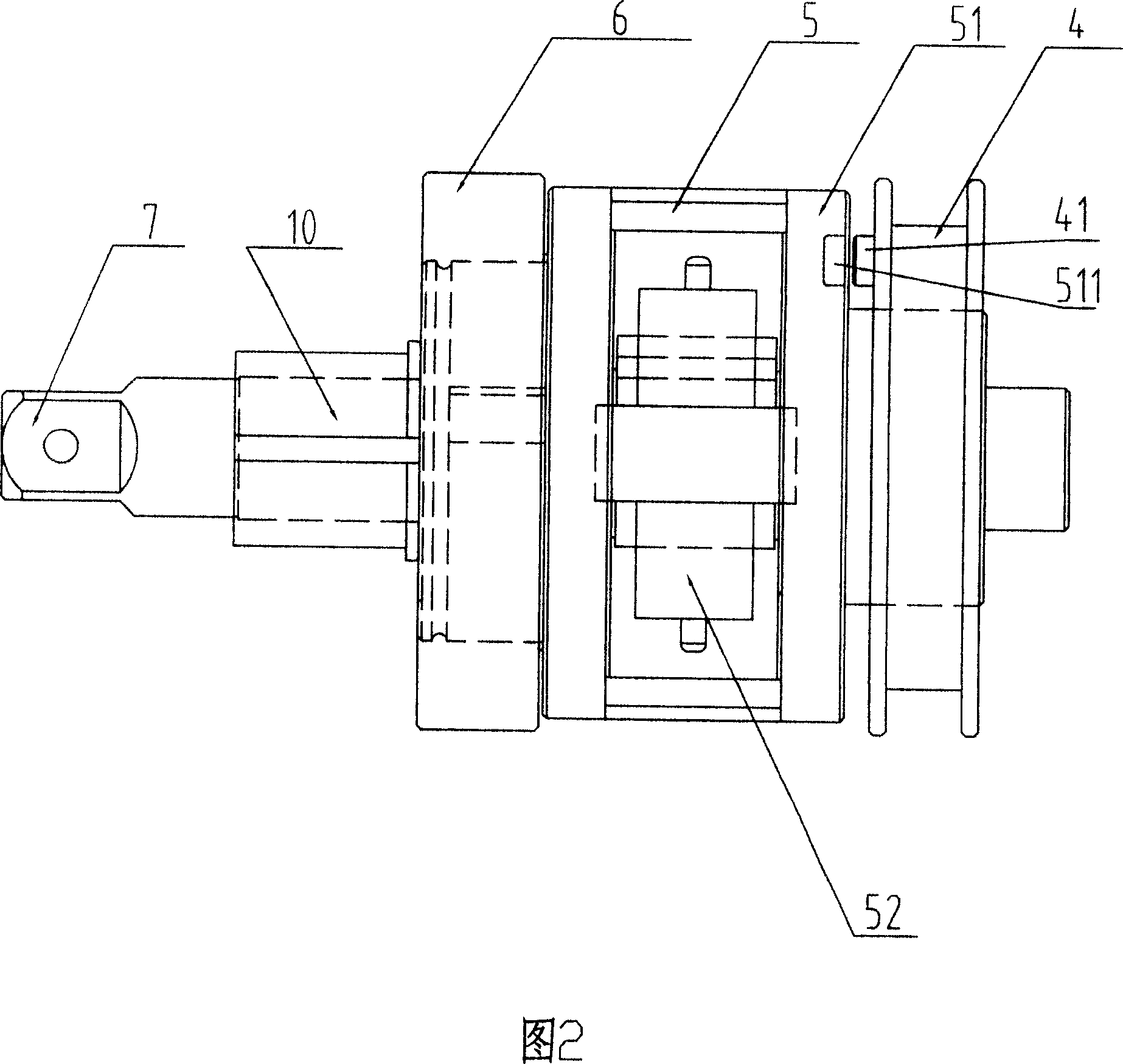
[0018] An electric wrench with convertible torque, which includes a housing 1, a motor 2 placed in the housing 1, a flywheel assembly connected to the power shaft of the motor 2, the flywheel assembly is connected to an output shaft 7, and the flywheel assembly is composed of a clutch assembly 3. The counterweight flywheel 4, the hollow flywheel assembly 5, and the reverse flywheel assembly 6 are sequentially matched and connected to form.

[0019] The clutch assembly 3 is composed of a frustum-shaped groove provided on the hollow flywheel 4 and a frustum-shaped friction clutch 15 arranged on the power shaft of the motor 2. The power shaft of the motor 2 is sleeved with a frustum-shaped friction clutch 15 and Compression spring 14 between motor 2 fuselages.

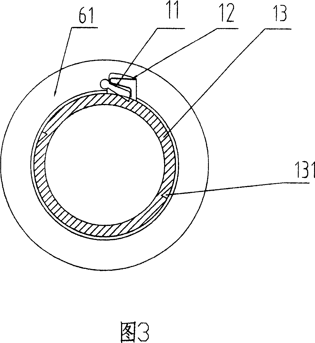
[0020] The hollow flywheel assembly 5 consists of a hollow flywheel 13 which is housed i...


PUM


Abstract

An electric wrench with convertible torque is composed of casing, motor with power axle, flywheel module connected to said power axle, and output axle linked with said flywheel module. Said flywheel module consists of a clutch unit, counterweight flywheel, hollow flywheel unit and reverse flywheel unit. It has the increased forward and reverse tensional forces.

Description

technical field [0001] The invention relates to the field of electric tools, in particular to a power transmission structure of an electric wrench. Background technique [0002] The output torque of the existing electric wrench on the market is constant. In the process of vehicle tire replacement, the friction force of fastening nut and loose nut is different, and the torque required by various vehicles is also different. Therefore, different vehicle models need different output torque. [0003] At present, the existing electric wrench on the market is in the process of starting and accelerating, which is overloaded and working with super large current, which will cause the fuse of the vehicle to burn out and shorten the service life of the motor. It is necessary to have a method that does not overload and does not generate super large current during the process of starting and accelerating. buffer device. Contents of the invention [0004] The object of the present inv...

Claims


Application Information

Patent Timeline
Patent Type & Authority Applications(China)
IPC IPC(8): B25B21/00B25B23/147B25B23/157
Inventor 章以扩陈以浙
Owner ZHEJIANG JINZI MACHINERY&ELECTRICAL
Learn More