Production of cavity molding shell member for cast-in-situs concrete

一种制作方法、空腔模的技术,应用在建筑构件、模具、制造工具等方向,能够解决整体强度和刚度差、空腔模壳构件破裂等问题

Inactive Publication Date: 2007-04-04
HUNAN QIUZEYOUZHUANLIZHANLVE PLANNING CO LTD
View PDF5 Cites 1 Cited by
  • Summary
  • Abstract
  • Description
  • Claims
  • Application Information

AI Technical Summary

Problems solved by technology

However, there is no reinforcing structure in the cavity formwork member, so the overall strength and rigidity of the cavity formwork member are poor, and the cavity formwork member is prone to breakage

Method used


Image

  • Production of cavity molding shell member for cast-in-situs concrete
  • Production of cavity molding shell member for cast-in-situs concrete
  • Production of cavity molding shell member for cast-in-situs concrete

Examples


Embodiment Construction

[0067] The present invention will be further described below in conjunction with the accompanying drawings and embodiments.

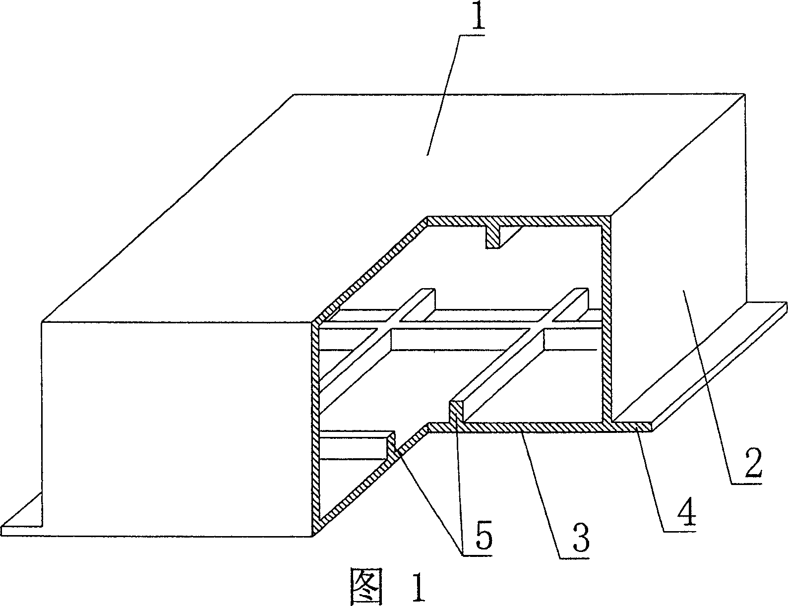
[0068] A method for manufacturing a cavity formwork member for cast-in-place concrete, characterized in that:

[0069] (1), making an open cavity formwork in the mould;

[0070] (2), make slurry lower bottom 3 at lower bottom mold;

[0071] (3), before the lower bottom (3) slurry is solidified and hardened, the opening edge of the pre-made open cavity formwork and the lower bottom slurry are bonded into a whole;

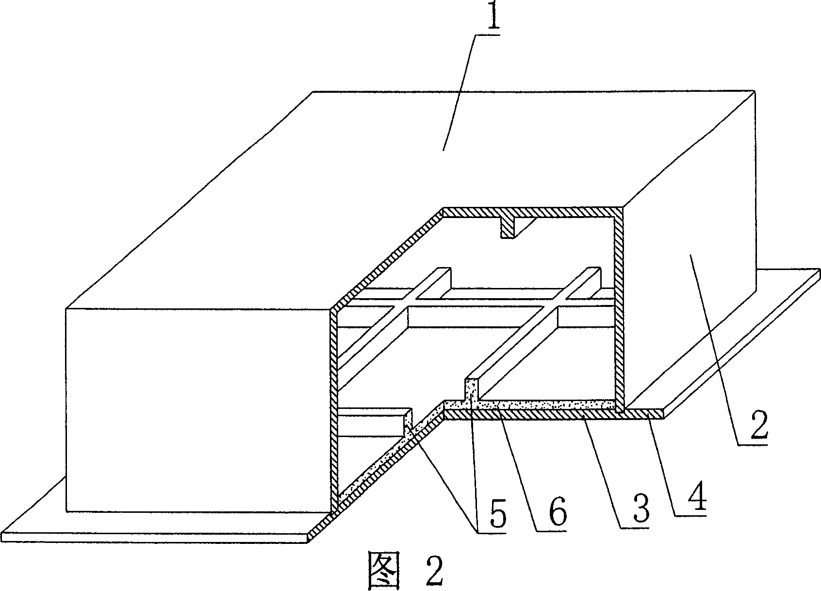
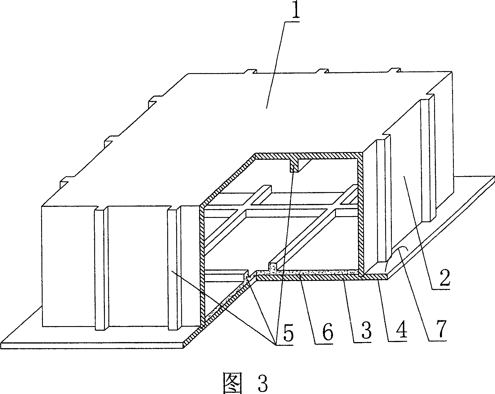
[0072] (4), maintenance demoulding. In the accompanying drawings, 1 is an upper plate, 2 is a surrounding side wall, 3 is a lower bottom, 4 is a pick plate, and 5 is a reinforcing rib. In the following drawings, those with the same number have the same description.

[0073] Another manufacturing method of a cavity formwork member for cast-in-place concrete, characterized in that:

[0074] (1), in the mould, make one layer of cementing mate...


PUM


Abstract

A method for preparing the hollow concrete shell member by in-situ pouring includes such steps as making a hollow concrete shell member with bottom opening by use of mould, pouring concrete bottom in a bottom mould, adhering said hollow concrete shell member with said concrete bottom before the concrete bottom is solidified, curing, and demoulding.

Description

[0001] This application is a divisional application of an invention patent application with a filing date of August 4, 2003, an application number of 03143759.1, and a title of "a cavity formwork component for cast-in-place concrete". (1) Technical field [0002] The invention relates to a manufacturing method of a cavity formwork component for cast-in-place concrete. (2) Background technology [0003] At present, the cast-in-place concrete hollow floor is a widely used floor structure. The lightweight permanent tire molds filled in it include various hollow tubes and boxes, and the boxes are hollow or solid. For example, the patent No. ZL99249798.1, which the applicant applied for on November 29, 1999, is a utility model patent named "fiber-reinforced thin-walled member for reinforced concrete filling", which discloses a thin-walled formwork member, including an upper plate, The surrounding side walls, the lower bottom, and the upper plate, the surrounding side walls and th...

Claims


Application Information

Patent Timeline
Patent Type & Authority Applications(China)
IPC IPC(8): B28B7/22B28B1/52E04B5/36
Inventor 邱则有
Owner HUNAN QIUZEYOUZHUANLIZHANLVE PLANNING CO LTD
Why Eureka
Try Eureka