
Non-power supply electronic watermeter

An electronic water meter, no power supply technology, used in measuring devices, instruments, measuring flow/mass flow, etc., can solve the problems of easy damage of electronic components, inability to guarantee reliability, and increased cost, and achieve improved feasibility, low cost, Reliable effect

Inactive Publication Date: 2007-04-04
TIANJIN JINNAN KAIDA ELECTRONIC CO LTD
View PDF0 Cites 1 Cited by
  • Summary
  • Abstract
  • Description
  • Claims
  • Application Information

AI Technical Summary

Problems solved by technology

[0002] The commonly used electronic water meter is a power supply type. The water meter needs to have secondary instrumentation devices such as data collectors and self-power supply systems. Electronic components are easily damaged in power outages or harsh environments, which increases costs and cannot guarantee its reliability.

Method used


Image

  • Non-power supply electronic watermeter
  • Non-power supply electronic watermeter
  • Non-power supply electronic watermeter

Examples


Embodiment Construction

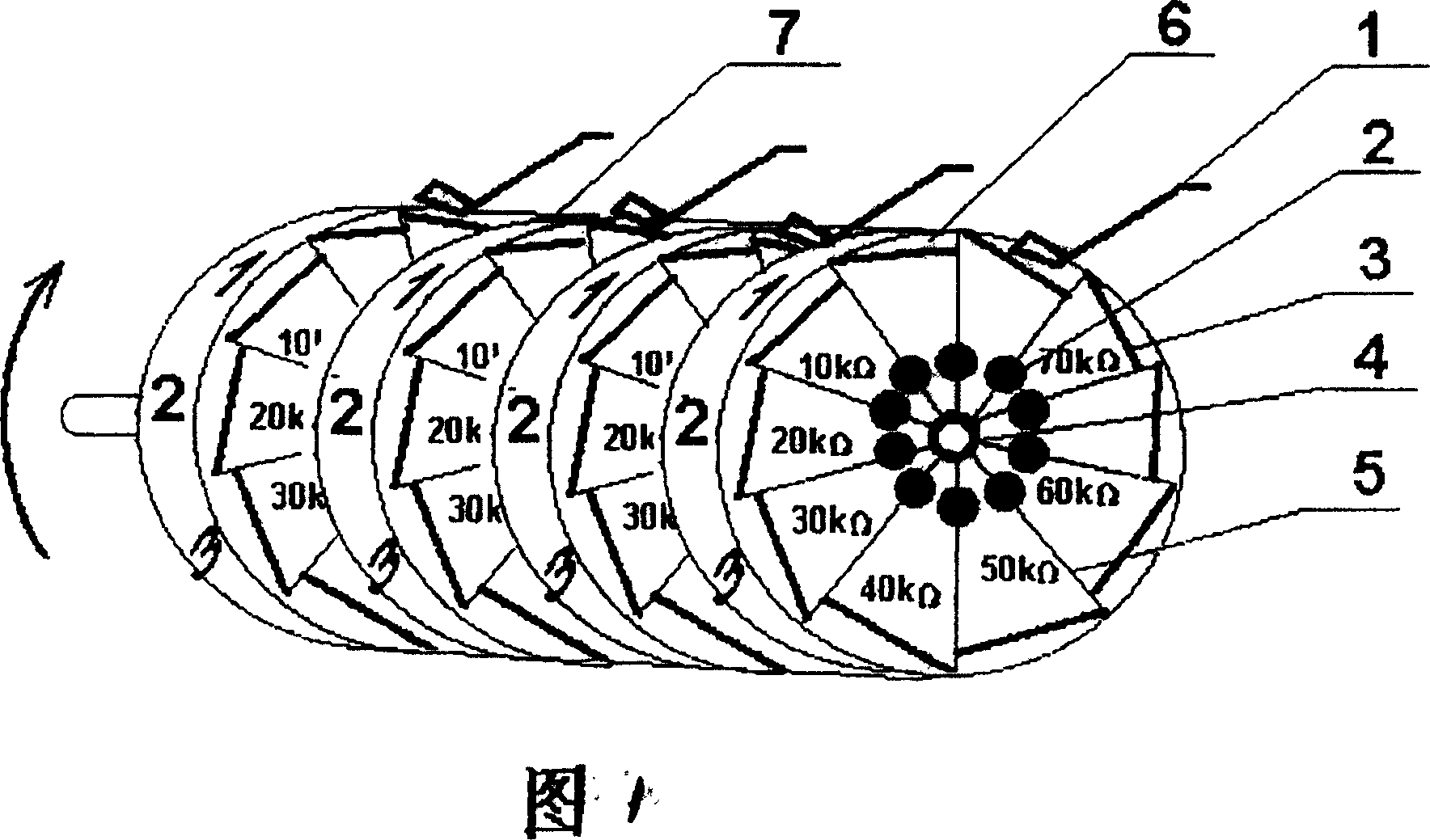
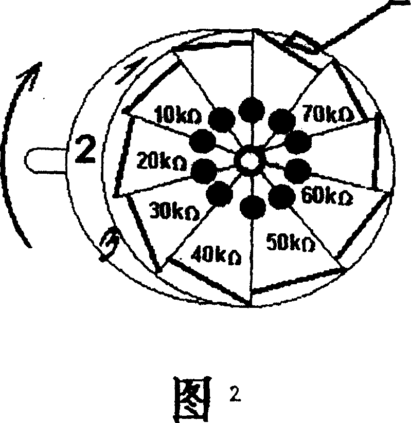
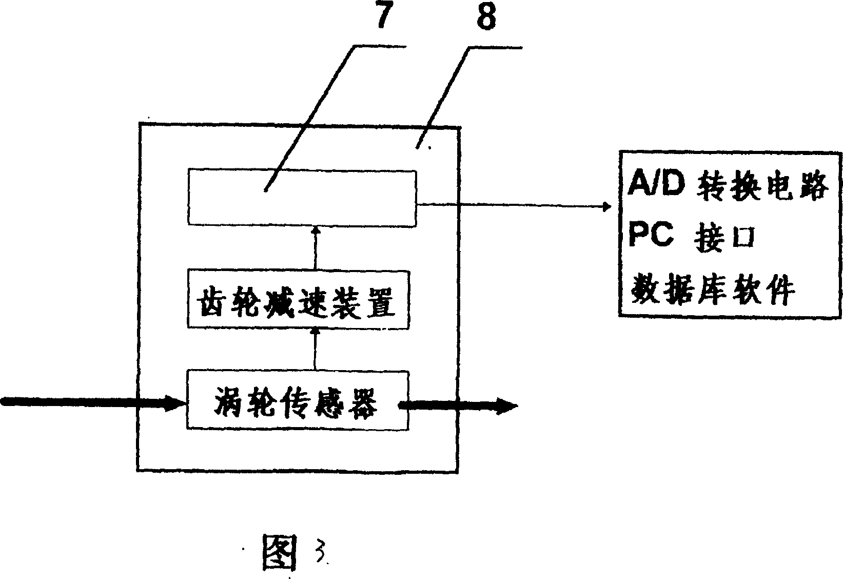
[0009] Please refer to the figure, a non-power electronic water meter, the water flow enters the water meter 8 from the water inlet, drives the turbine sensor to rotate, transmits the power brought by the turbine through the gear reduction device, and reduces the gear speed at the same time, drives the rotation segment with a certain gear transmission ratio Type potentiometer composite mechanical counter 7, the counter 7 is composed of 4-5 unit counting disc wheel 6, the toothed contact 3 corresponding to the number displayed by the counting disc wheel 6 is in contact with the brush 1 in the tangential direction, thereby Make the shaft core 4 of the transmission shaft as the negative electrode degree and the corresponding chip resistors 2 with different resistance values, the corresponding toothed contacts 3 and the brushes 4 to form an electrical path through the wires 5, and this can be obtained through the A / D conversion circuit. The electrical parameters of the time resista...


PUM


Abstract

An electronic water meter of power supply free type is prepared as setting contacts at periphery of character wheel on counting disc in counter, contacting electric brush with these contacts, arranging paster resistances with different resistance values on wire between contacts and shaft core of driving shaft and corresponding them to digits on character wheel of counting disc one by one.

Description

technical field [0001] The invention relates to a non-power electronic water meter. Background technique [0002] The conventional electronic water meter is a power supply type. The water meter needs to have secondary instrument devices such as data collectors and self-power supply systems. The electronic components are easily damaged in power outages or harsh environments, which not only increases the cost, but also cannot guarantee its reliability. SUMMARY OF THE INVENTION [0003] The purpose of the present invention is to overcome the above-mentioned defects and provide a powerless electronic water meter. [0004] The technical scheme of the present invention is a non-power electronic water meter, which is characterized in that: it includes a turbine sensor, a gear reducer, and a counter, and a contactor is provided around the count disc wheel of each unit in the rotary segment potentiometer compound mechanical counter. point, the brush is in contact with the contact,...

Claims


Application Information

Patent Timeline
Patent Type & Authority Applications(China)
IPC IPC(8): G01F1/075G01F15/00
Inventor 崔连凯
Owner TIANJIN JINNAN KAIDA ELECTRONIC CO LTD
Learn More