Horizontal pushing mechanism in H section steel production line
What is Al technical title?
Al technical title is built by PatSnap Al team. It summarizes the technical point description of the patent document.
A production line, H-beam technology, applied in auxiliary devices, auxiliary welding equipment, welding/cutting auxiliary equipment, etc., to achieve the effect of high efficiency, convenient adjustment, and reduction of potential safety hazards
Inactive Publication Date: 2012-05-23
WUXI HUALIAN PRECISION MACHINERY
View PDF6 Cites 0 Cited by
Summary
Abstract
Description
Claims
Application Information
AI Technical Summary
This helps you quickly interpret patents by identifying the three key elements:
Problems solved by technology
Method used
Benefits of technology
Problems solved by technology
This method of adjusting H-shaped steel has extremely low work efficiency and high labor intensity. It requires a large number of workers to work at the same time to meet the production requirements. In addition, there are great safety hazards in manual operation, and the degree of automation is low.
Method used
Image
Click on the blue label to locate the original text in one second.
Reading with bidirectional positioning of images and text.
Examples
Embodiment Construction
[0012] Below the present invention will be further described in conjunction with the embodiment in the accompanying drawing:
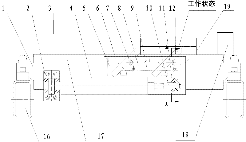
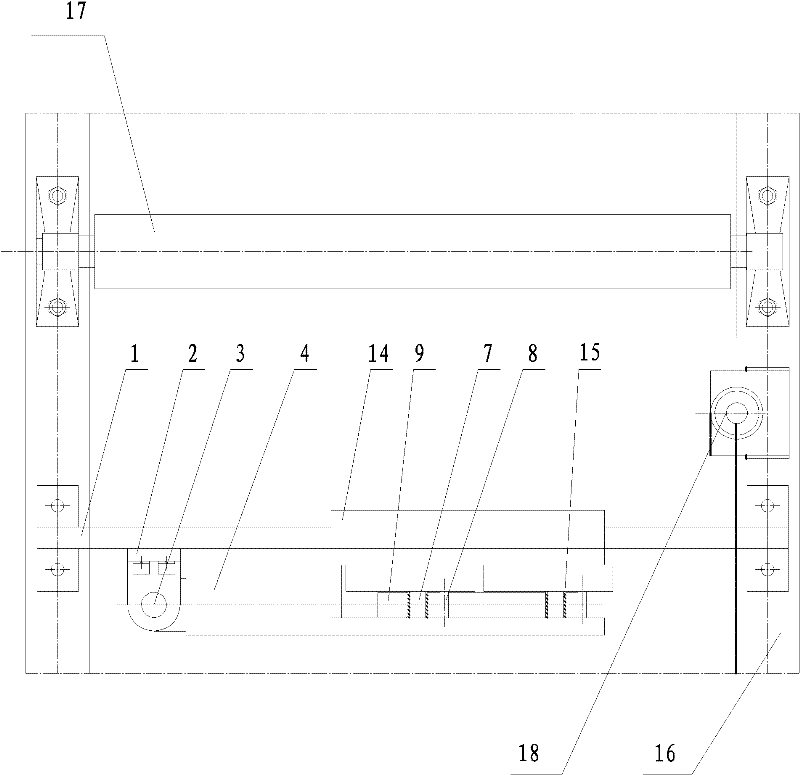
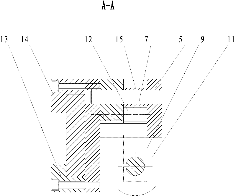
[0013] Such as Figure 1 ~ Figure 3 As shown, it includes guide plate 1, oil cylinder seat 2, first pin shaft 3, oil cylinder 4, moving body 5, pusher block 6, second pin shaft 7, third pin shaft 8, pulling body 9, oil cylinder joint 10, Block 11, fourth pin shaft 12, first briquetting block 13, second briquetting block 14, spacer 15, frame 16, roller table 17, positioning wheel 18 and workpiece 19.
[0014] In the present invention, the guide plate 1 and the oil cylinder seat 2 are connected by bolts, one end of the oil cylinder 4 is connected to the oil cylinder seat 2 through the first pin shaft 3, the other end is connected to the pulling body 9 by bolts through the oil cylinder joint 10, and the stopper 11 is welded to the moving body 5 Connection, the first briquetting block 13 and the second briquetting block 14 are connected with the moving bo...
PUM
Abstract
The invention relates to a horizontal pushing mechanism in an H section steel production line comprising a guide plate, an oil cylinder seat, a first pin shaft, an oil cylinder, a moving body, a material pushing block, a second pin shaft, a third pin shaft, a pulling body, an oil cylinder joint, a baffle plate, a fourth pin shaft, a first pressing block, a second pressing block, a spacer sleeve, a stand, a roller bed, a locating wheel and a workpiece, wherein the guide plate and the oil cylinder seat are connected by bolts, one end of the oil cylinder is connected with the oil cylinder seat through the first pin shaft, the other end is connected with the pulling body by the bolts through the oil cylinder joint, the baffle plate and the moving body are connected through welding, the first pressing block and the second pressing block are connected with the moving body through the bolts, the material pushing block and the spacer sleeve are fixed on the moving body by using the second pinshaft, the roller bed and the locating wheel are fixed on the stand by bolts, and the workpiece is placed on the roller bed. The invention has convenient and fast regulation, accurate locating, high degree of automation, suitability for alignment regulation work when a large scale of H section steels are produced, high efficiency, less labor intensity and reduced potential safety hazard.
Description
technical field [0001] The invention relates to an adjusting horizontal pushing mechanism in an H-shaped steel production line, specifically a device for aligning and adjusting H steel on the line before automatic welding of H steel plates, and belongs to the technical field of mechanical equipment. [0002] Background technique [0003] In the prior art, when adjusting the alignment of the H-shaped steel, the adjustment is usually carried out by combining crane hoisting and manual operation. This method of adjusting H-beams has extremely low work efficiency and high labor intensity. It requires a large number of workers to work at the same time to meet the production requirements. Moreover, manual operation also has great potential safety hazards, and the degree of automation is low. Contents of the invention [0004] The object of the present invention is to overcome the above disadvantages, thereby providing a horizontal pushing mechanism in the H-shaped steel productio...
Claims
Application Information
Patent Timeline
Application Date:The date an application was filed.
Publication Date:The date a patent or application was officially published.
First Publication Date:The earliest publication date of a patent with the same application number.
Issue Date:Publication date of the patent grant document.
PCT Entry Date:The Entry date of PCT National Phase.
Estimated Expiry Date:The statutory expiry date of a patent right according to the Patent Law, and it is the longest term of protection that the patent right can achieve without the termination of the patent right due to other reasons(Term extension factor has been taken into account ).
Invalid Date:Actual expiry date is based on effective date or publication date of legal transaction data of invalid patent.