
Method for decoding optical storage system

An optical storage and decoding technology, applied in the field of decoding, can solve problems such as deviation and affecting the bit decoding results of the back-end channel

Inactive Publication Date: 2007-04-04
LITE ON IT
View PDF0 Cites 0 Cited by
  • Summary
  • Abstract
  • Description
  • Claims
  • Application Information

AI Technical Summary

Problems solved by technology

Due to the influence of noise and interference, the detected channel bit RF value usually deviates from the ideal RF value level. When the error is too large, it may affect the decoding result of the back-end channel bit.

Method used


Image

  • Method for decoding optical storage system
  • Method for decoding optical storage system
  • Method for decoding optical storage system

Examples


Embodiment Construction

[0037] Some embodiments of the invention are described in detail below. However, the present invention can also be widely implemented in other embodiments except for the content described in detail, and the scope of the present invention is not limited, which is subject to the scope of the subsequent patent applications.

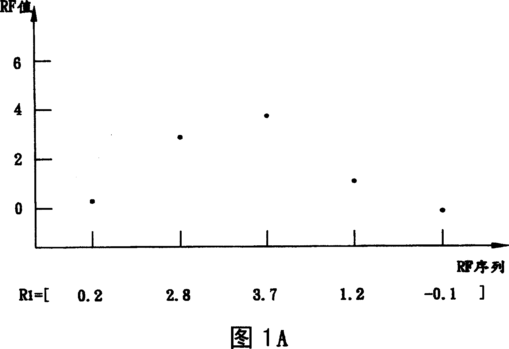
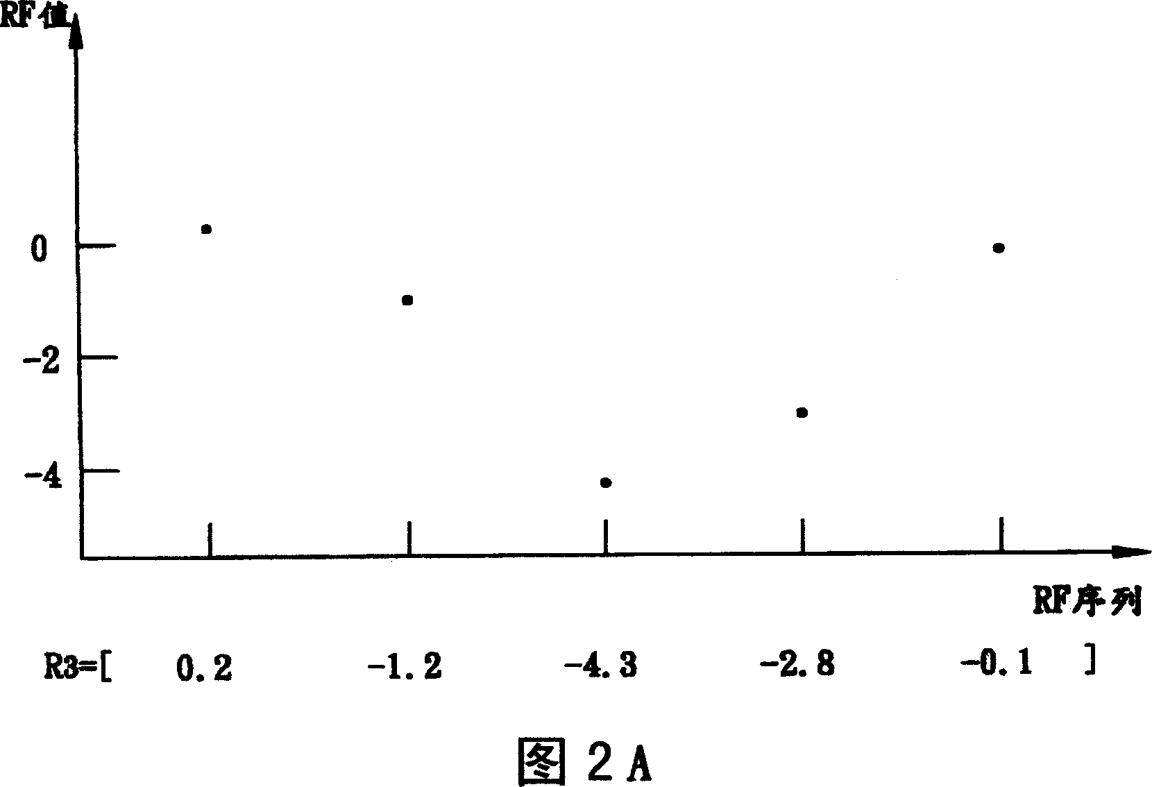
[0038] First of all, it must be explained that, on an optical disc, generally the places where the pits and lands are transformed represent a channel bit "1", and the flat pits and lands represent a "0". It is known from the description of the prior art that RLL(m, n) restricts that there must be at least m and at most n "0"s between two consecutive "1". In other words, corresponding to the pits and lanes on the optical disc, the characteristics of RLL coding limit the length of the pits and lanes in each segment. In the embodiment of the present invention, the representation method of the channel bit is to represent the pit with "-1" and the lane with "1"....


PUM


Abstract

A code translation method is capable of memorizing bite array on the disk through partial max response detecting. Different to traditional method, this method doesn't aim at radio frequency signal, but an ideal radio frequency signal so to decrease error rate. The method includes the following procedures: acquiring the first radio frequency signal array; detecting a certain signal in the radio frequency signal array; adjusting multi signals of the radio frequency signal array into ideal radio frequency signal and forming the second radio frequency signal array; code translation of the second radio frequency signal array.

Description

technical field [0001] The present invention relates to a decoding method, in particular to a decoding of an optical storage system. The radio frequency value of an optical signal is adjusted to reduce the channel bit decoding error rate. Background technique [0002] Coding is an important part of digital systems, especially digital communication and data storage systems. In general, coding can be divided into three categories: source coding, error control coding, and channel coding. The purpose of source coding is to convert information, which may be a human or computer source, into a sequence of digital data, especially a sequence of binary bits, and to compress the content of the message; error control coding encodes the sequence of digital data into a new bit Sequence, so that this bit sequence has the protection function of error signal detection and correction; and the purpose of channel coding is to more efficiently modulate the bit sequence to the communication cha...

Claims


Application Information

Patent Timeline
Patent Type & Authority Applications(China)
IPC IPC(8): G11B20/10G11B7/00H03M7/46
Inventor 张佳彦
Owner LITE ON IT
Features
  • Generate Ideas
  • Intellectual Property
  • Life Sciences
  • Materials
  • Tech Scout
  • Unparalleled Data Quality
  • Higher Quality Content
  • 60% Fewer Hallucinations
Learn More