Chargeable circuit, integrated circuit and controlling method

A charging circuit, integrated circuit technology, applied in transducer circuits, electrical components, sensors, etc.

Inactive Publication Date: 2007-04-04
PRINCETON TECHNOLOGY
View PDF0 Cites 2 Cited by
  • Summary
  • Abstract
  • Description
  • Claims
  • Application Information

AI Technical Summary

Problems solved by technology

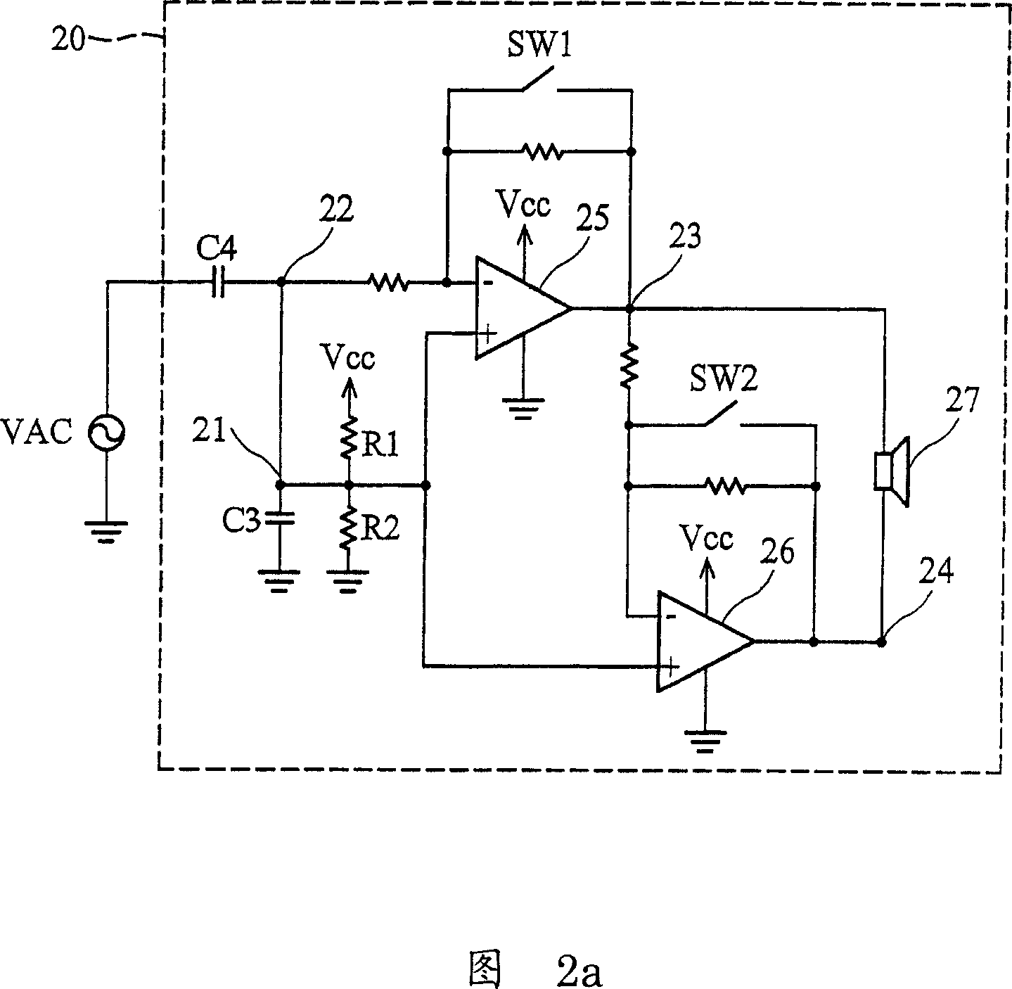
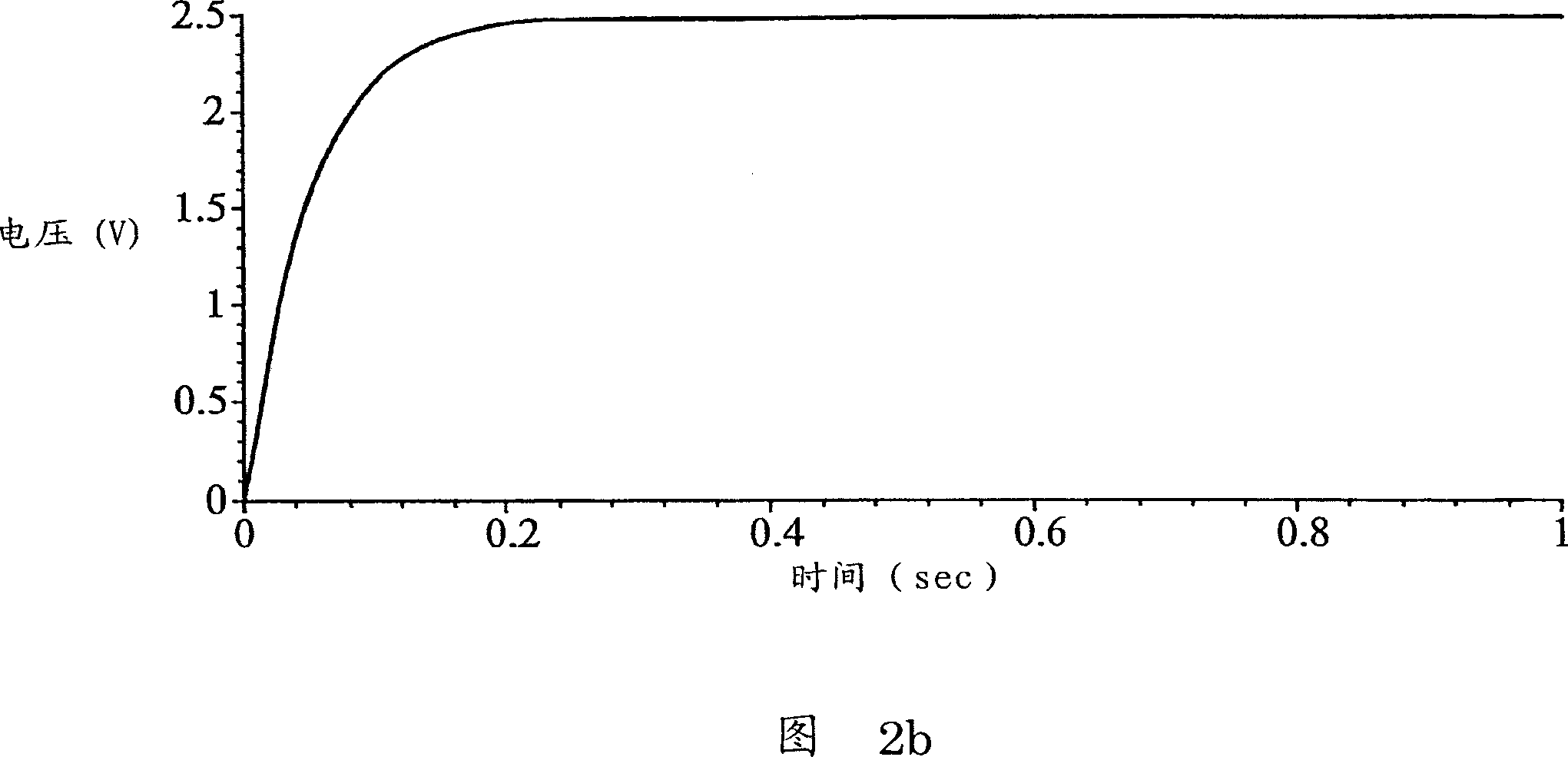
As shown in the figure, at time t1, although the voltage of the node 201 is 2.5V, the voltage of the node 202 is not yet equal to 2.5V, so there is a voltage difference of about 200mV between the two ends of the speaker 207

Method used


Image

  • Chargeable circuit, integrated circuit and controlling method
  • Chargeable circuit, integrated circuit and controlling method
  • Chargeable circuit, integrated circuit and controlling method

Examples


Embodiment Construction

[0052] In order to make the above-mentioned and other objects, features and advantages of the present invention more obvious and understandable, the following specifically enumerates the preferred embodiments, in conjunction with the accompanying drawings, which are described in detail as follows:

[0053] Figure 4 is a schematic diagram of the integrated circuit of the present invention. As shown in the figure, the integrated circuit is used to drive the load unit 3, which includes a reference capacitor 31, an amplifying unit 32, and a charging circuit 33. The reference capacitor 31 is used to store a reference voltage Vc. The amplifying unit 32 drives the load unit 3 according to a sound signal VAC and a reference voltage Vc. The amplifying unit 32 and the load unit 3 may constitute a bridged load (BTL).

[0054] The charging circuit 33 includes a power supply unit 331 and a comparison unit 332. The power supply unit 331 provides the first voltage V1 or the second voltage V2 to ...


PUM


Abstract

The charging circuit is used for bridge type load with an amplifying unit and a load unit. The amplifying unit drives load unit according to audio signals and reference voltage; the reference voltage is saved in a reference capacitor. The charging circuit comprises a power unit and a comparator; the power unit provides a first reference voltage and a second reference voltage; when the reference voltage is lower than a first preset value, the comparator disenables the control signal for providing the first voltage for the capacitor; when the reference voltage is higher than or equal to the first preset value and is lower than the second preset value, the comparator enables the control signals for providing a second voltage for the reference capacitor.

Description

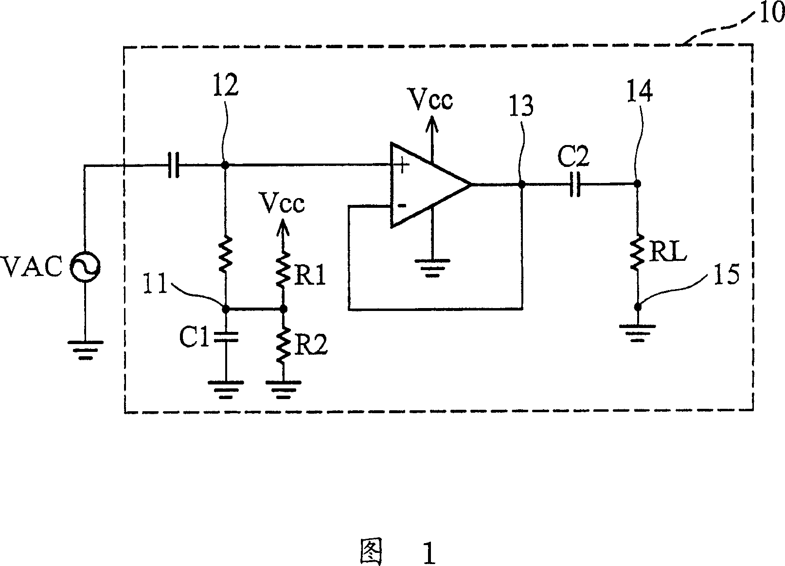
Technical field [0001] The present invention relates to a charging circuit, in particular to a charging circuit suitable for Bridge Tied Load (BTL). Background technique [0002] Figure 1 shows a schematic diagram of an existing bridged load. When the resistances of the resistors R1 and R2 are equal, if the power supply Vcc is provided to the bridge load 10 and the sound signal VAC has not been provided to the bridge load 10, the capacitor C1 starts to charge. When the voltage of the node 11 is equal to Vcc / 2, the capacitor C1 will stop charging. The voltage of node 12 will be approximately equal to the voltage of node 11. According to the characteristics of the amplifier, the voltage of node 13 will also be equal to Vcc / 2. [0003] Since the load RL is coupled between the nodes 14 and 15 and the node 15 is grounded, the voltage of the node 14 will be equal to the voltage of the node 15. However, when the voltages of the nodes 13 and 14 are different, the capacitor C2 will start ...

Claims


Application Information

Patent Timeline
Patent Type & Authority Applications(China)
IPC IPC(8): H04R3/00H03F1/00
Inventor 李勇明
Owner PRINCETON TECHNOLOGY
Why Eureka
Try Eureka