

Ceramic heater and manufacturing method thereof, and glow plug using ceramic heater
A technology of ceramic heaters and heating parts, applied in the directions of combustion method, heating element material, heating element shape, etc.
- Summary
- Abstract
- Description
- Claims
- Application Information
AI Technical Summary
Problems solved by technology
Method used
Image

Examples
example 1
[0087] First, samples of the green resistor element 200 with the bumps 4 arranged in the green heating portion 231 and samples of the green resistor element 200 without the bumps were injection molded and taken out from the mold. It was checked whether defects such as cracks occurred in the green heating portion 231 of each sample. That is, samples of the green resistor element 200 of the present invention having the protrusions 4 in the green heating portion 231 of the example, and samples of the green resistor element 200 of the comparative example not having the protrusions 4 were produced. . The samples of the present invention were molded by means of molds 51, 61 configured such that in the green heating part 231, the portion P7 of the protrusion 4 was pushed out by the ejector pin T7. The sample of the comparative example was molded by a mold in which the ejector pin was not placed at the position corresponding to the above. Both the sample of the present invention and...
example 2
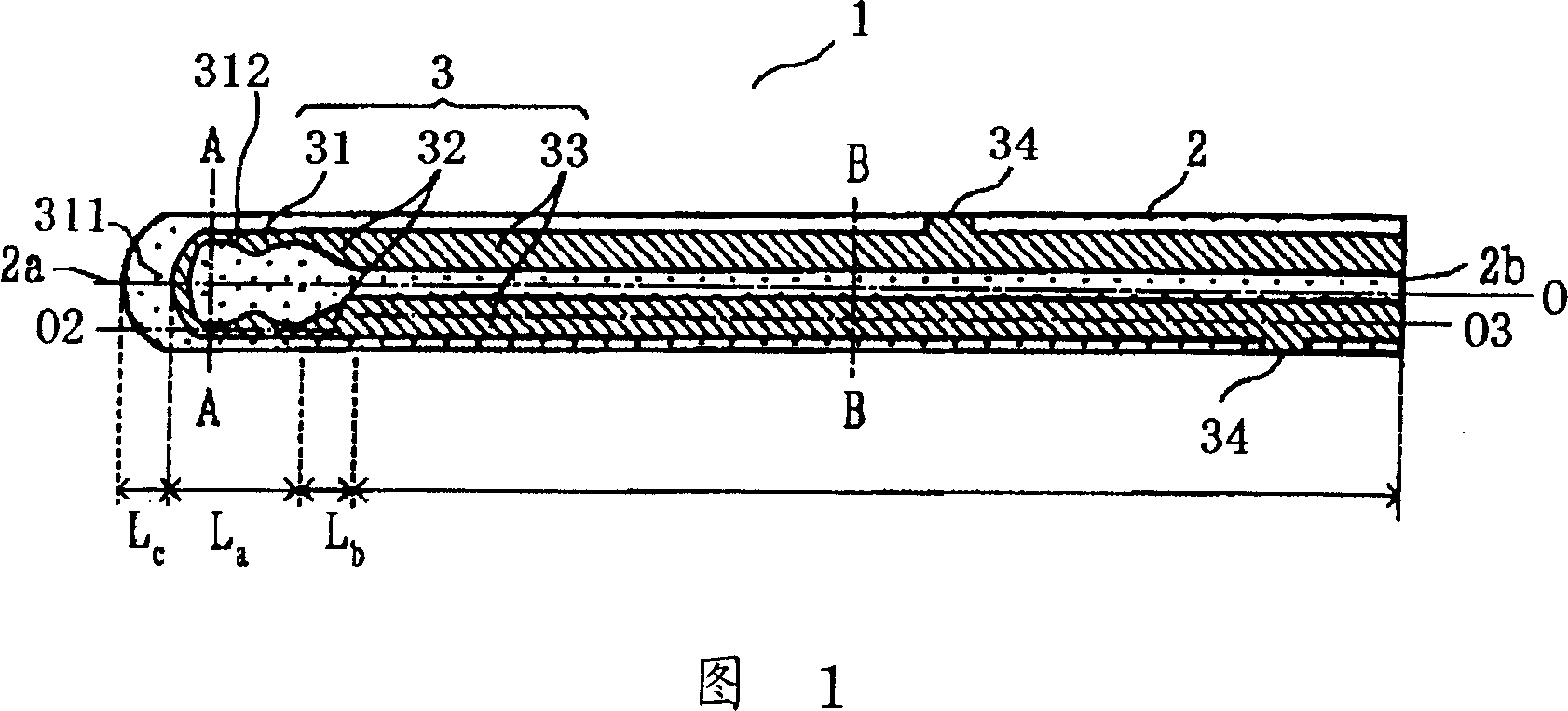
[0091] Next, a resistor element 3 made of conductive ceramics and having a continuously formed heating portion 31 and a pair of lead portions 33 is embedded in a rod-shaped support 2 made of insulating ceramics to produce a 1 configured as shown in FIG. Ceramic heater 1 to sample No. 6. Using the ceramic heater 1, a glow plug 20 for starting a diesel engine and having a configuration shown in FIG. 7 was produced.
[0092] The insulating ceramic used to construct support 2 is 96.5 (0.89Si 3 N 4 -0.08Er 2 o 3 -0.01V 2 o 5 -0.02WO 3 )-3.5MoSi 2 (weight ratio). The conductive ceramic constructing the resistor element 3 is 70WC / 30Si 3 N 4 -3.96Er 2 o 3 -1.61SiO2 2 (weight ratio).
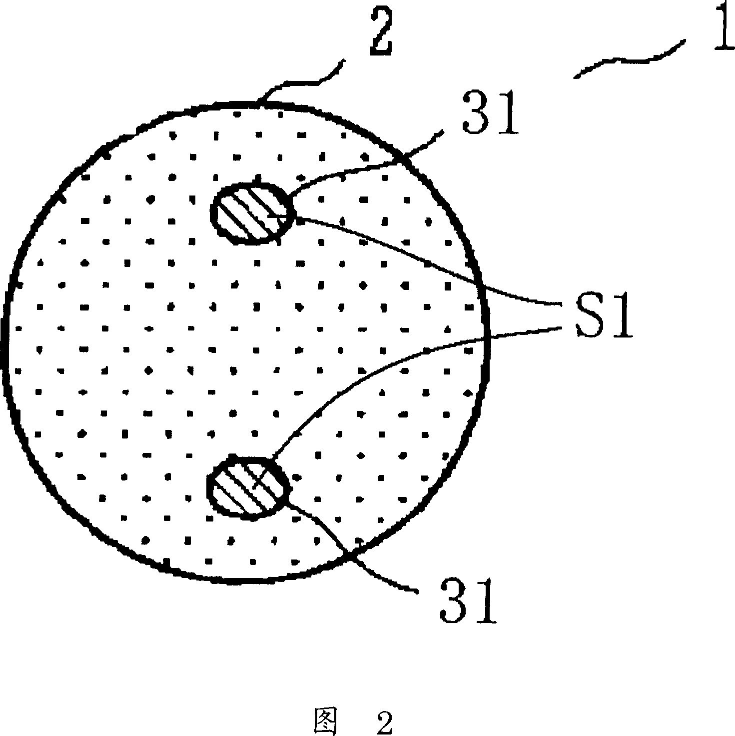
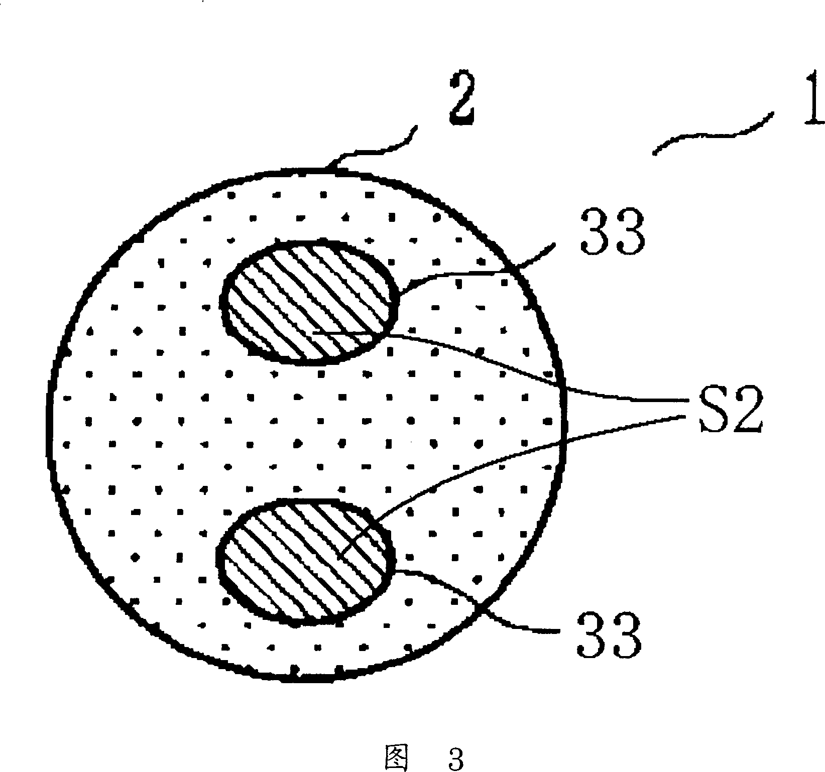
[0093] The cross-sectional shapes of the ceramic heaters 1 of samples Nos. 1 to 6 in the longitudinal direction were three kinds of cross-sectional shapes shown in FIGS. 8 to 10 . Sample Nos. 1 and 5 had the shapes shown in FIG. 8 , samples Nos. 2 and 3 had the shapes shown in FIG. 9 , and...
example 3
[0109] Next, in order to examine the influence on the resistance (R1) of the resistor element 3, while changing the resistance (R1) of the resistor element 3 by changing the sintering temperature in the range of 1,700 to 1,800°C, the The material and shape of the produced ceramic heater 1 are the same as those of the ceramic heater. At this time, the resistance ( R1 ) of the resistor element 3 is 249 to 478 mΩ. Using this ceramic heater 1, glow plugs 20 of samples Nos. 7 to 10 for starting diesel engines were produced.
[0110] In the glow plug 20 , the energy consumption when the glow plug was heated to 1,250° C., the heating temperature per watt, and the period of time to reach 1,000° C. when 11 V was applied were measured. The results are shown in Table 7.
[0111] sintering
[0112] As shown in Table 7, the energy consumption when the glow plugs were heated to 1,250° C. was substantially the same as each other, and the heating temperature per watt was also su...
PUM
| Property | Measurement | Unit |
|---|---|---|
| electrical resistance | aaaaa | aaaaa |
| diameter | aaaaa | aaaaa |
| area | aaaaa | aaaaa |
Abstract
Description
Claims
Application Information