Automatic centering central frame

An automatic centering and centering technology, which is used in positioning devices, large fixed members, manufacturing tools, etc., can solve complex and high processing and manufacturing requirements, and achieve the effect of simple operation, convenient operation and wide application range.

Inactive Publication Date: 2007-04-11
HUAZHONG UNIV OF SCI & TECH
View PDF2 Cites 9 Cited by
  • Summary
  • Abstract
  • Description
  • Claims
  • Application Information

AI Technical Summary

Problems solved by technology

Due to the use of end face threads and gear boxes, the center frame is relatively complicated and has high requirements for processing and manufacturing.

Method used


Image

  • Automatic centering central frame
  • Automatic centering central frame
  • Automatic centering central frame

Examples


Embodiment Construction

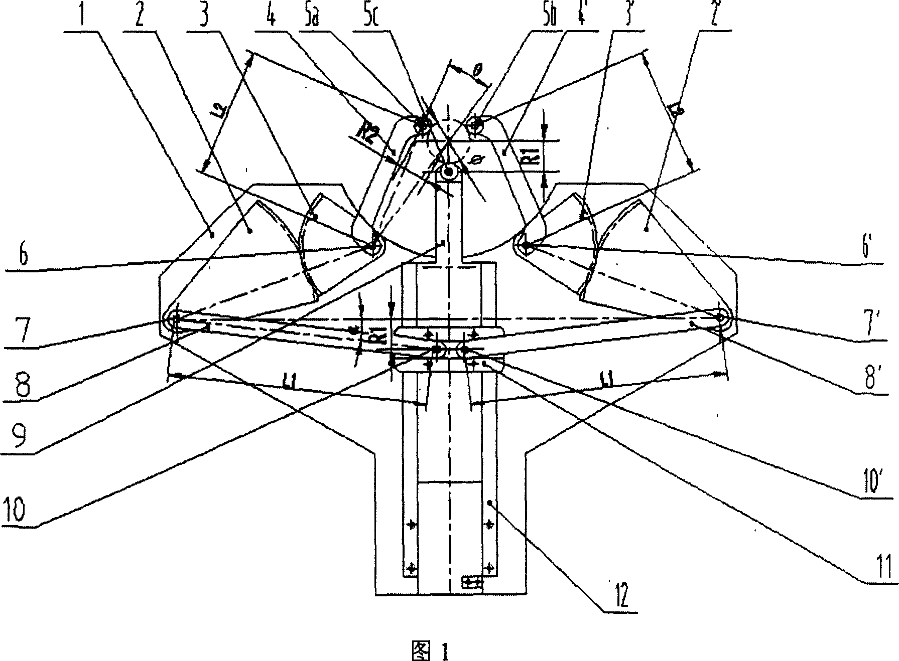
[0012] As shown in FIG. 1, the lower pressing rod slide rail 12 is fixed in the middle of the bracket 1, and the lower pressing rod 9 is located on the lower pressing rod slide rail 12 and can slide up and down along the lower pressing rod slide rail 12. A chute block 11 is installed on the lower pressing rod 9. The left large sector gear 2 and the left connecting rod 8 are fixedly connected, and are connected to the bracket 1 through the lower left rotation pin 7, and the right large sector gear 2'and the right connecting rod 8'are fixedly connected, and are connected to the bracket 1 through the right lower rotation pin 7' The upper part can be rotated around the left and right lower revolving pins 7, 7'respectively. The lower left revolving pin 7 and the lower right revolving pin 7'are symmetrically arranged on the bracket 1 relative to the lower pressing rod slide rail 12. One ends of the left connecting rod 8 and the right connecting rod 8'are respectively mounted on the brac...


PUM


Abstract

The automatically centering central frame consists of support, left large sector gear, left small sector gear, left pressure lever, right pressure lever, roller, upper rotary pin, right small sector gear, right large sector gear, link rod, sliding block, runner block, lower pressure lever slide rail, lower pressure lever and lower rotary pin. It is one opened structure and realizes three bearing point automatic centering by means of the block-link rod mechanism to drive the sector gear mechanism. The complete linkage of the three bearing points can center shaft work piece of different diameter reliably in the same rotary center. The present invention has the features of reliable design, simple structure, wide application range, etc and is especially suitable for automatic control of central frame by means of pneumatic, hydraulic or other modes.

Description

Technical field [0001] The invention relates to a machine tool clamping aid, in particular to an automatic centering center frame. Background technique [0002] In the field of machinery manufacturing, when turning or grinding slender shaft workpieces, a center frame is often used to support the workpiece to improve rigidity and ensure machining accuracy. The center frame generally adopts the principle of three-point fixed circle to support the slender shaft workpiece. The three supporting points of the existing machine tool center frame generally cannot be linked. For shaft workpieces of different diameters, the positions of the three points need to be manually adjusted to make the center of the circle determined by the three points located on the center of rotation of the machine tool, such as: Chinese utility model Patent: "Adjustable Center Frame" (ZL 200420027852.1), etc. This process often requires the use of dial gauges, needle dials and other measuring tools, relying on t...

Claims


Application Information

Patent Timeline
Patent Type & Authority Applications(China)
IPC IPC(8): B23B23/00B23Q3/18B23Q1/25B23Q1/76
Inventor 段正澄黄禹李斌李勇
Owner HUAZHONG UNIV OF SCI & TECH
Why Eureka
Try Eureka