Automatic light regulating energy saving lamp
An automatic dimming, energy-saving lamp technology, applied in the direction of energy-saving control technology, light source, electric light source, etc., can solve the problems of difficulty in large-scale promotion, inconvenience, unaccustomed, etc., to expand the scope of monitoring, broaden the scope of application, and optimize the environment. Effect
- Summary
- Abstract
- Description
- Claims
- Application Information
AI Technical Summary
Problems solved by technology
Method used
Image

Examples
Embodiment 1
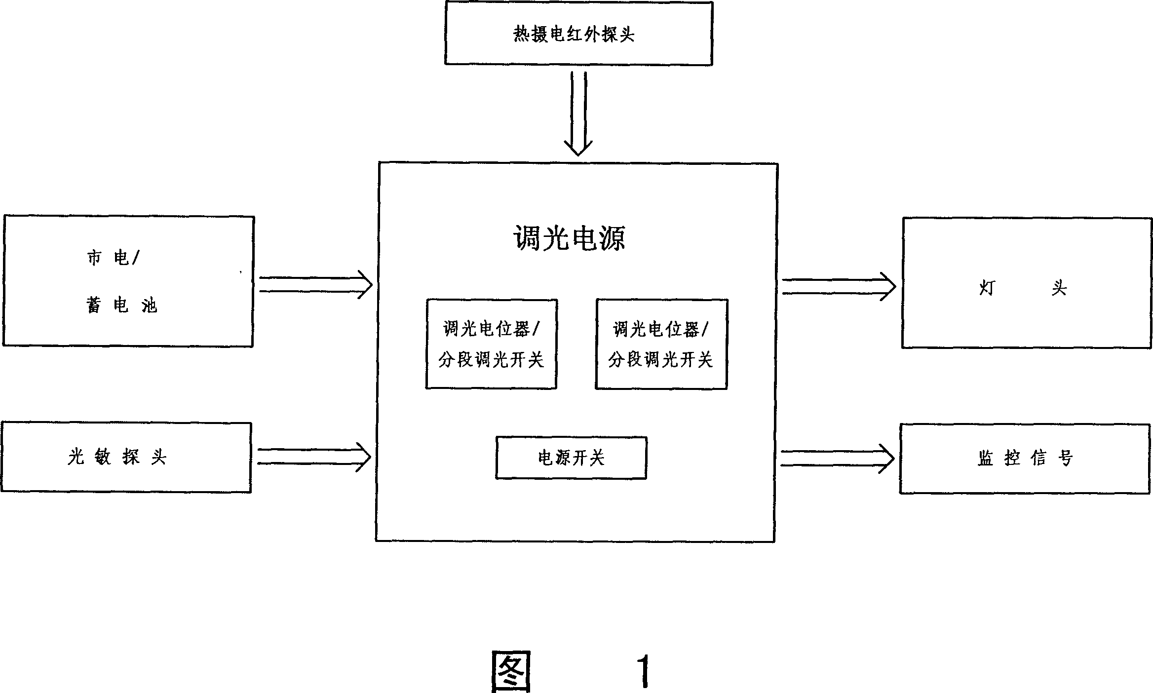
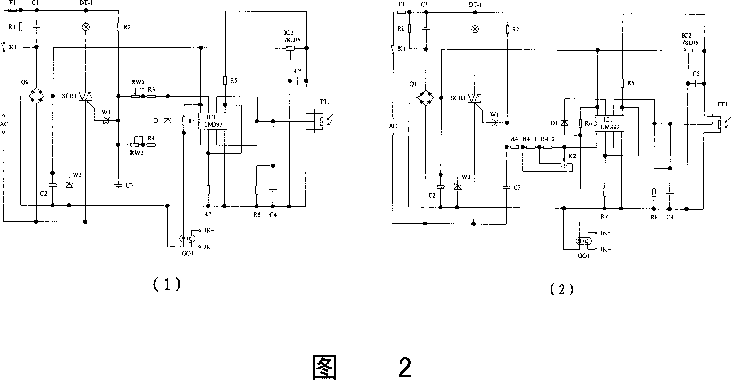
[0042] See (1) in Figure 2. As shown in the figure is a schematic diagram of an AC-AC dimming power supply with a bidirectional thyristor (SCR1) as a switching element and two dimming potentiometers (RW1) and (RW2).
[0043]In the figure, the power consumption of the lamp head (DT-1) is taken from the mains (AC) through the triac (SCR1), so the current flowing through the lamp head is also AC; the trigger resistor (R2) and the delay capacitor (C3) and The stepped Zener diode (W1) forms a delay trigger, which provides an initial trigger time for the thyristor (SCR1) and determines the maximum brightness of the lamp head (DT-1); The detected signal is filtered by the capacitor (C4) and the resistor (R8), and then input to the dual voltage comparator (IC1-LM393), and then the seventh pin and the second pin of the dual voltage comparator (IC1-LM393) Output two levels of high and low changes, and absorb the current of the trigger resistor (R2) through the dimming potentiometer (RW...
Embodiment 2
[0046] See (2) in Figure 2. As shown in the figure is a schematic diagram of an AC-AC dimming power supply with a bidirectional thyristor (SCR1) as a switching element and only one segmental dimming switch (K2).
[0047] This embodiment cancels the dimming potentiometer (RW1) that can adjust the brightness of the lamp head when there are people in the previous figure, and replaces the dimming potentiometer that can adjust the darkness of the lamp head when there is no one with a segmental dimming switch (K2) (RW2), in addition to the original resistor (R4), two series resistors (R4+1) and (R4+2) are added; the segmental dimming switch (K2) is a three-state switch, which is compatible with the above three With only the combination of resistors, three different grades of darkness of the lamp head when no one is present can be obtained.
[0048] Compared with the previous figure, this embodiment has two differences. One: After canceling the dimming potentiometer (RW1), it is imp...
Embodiment 3
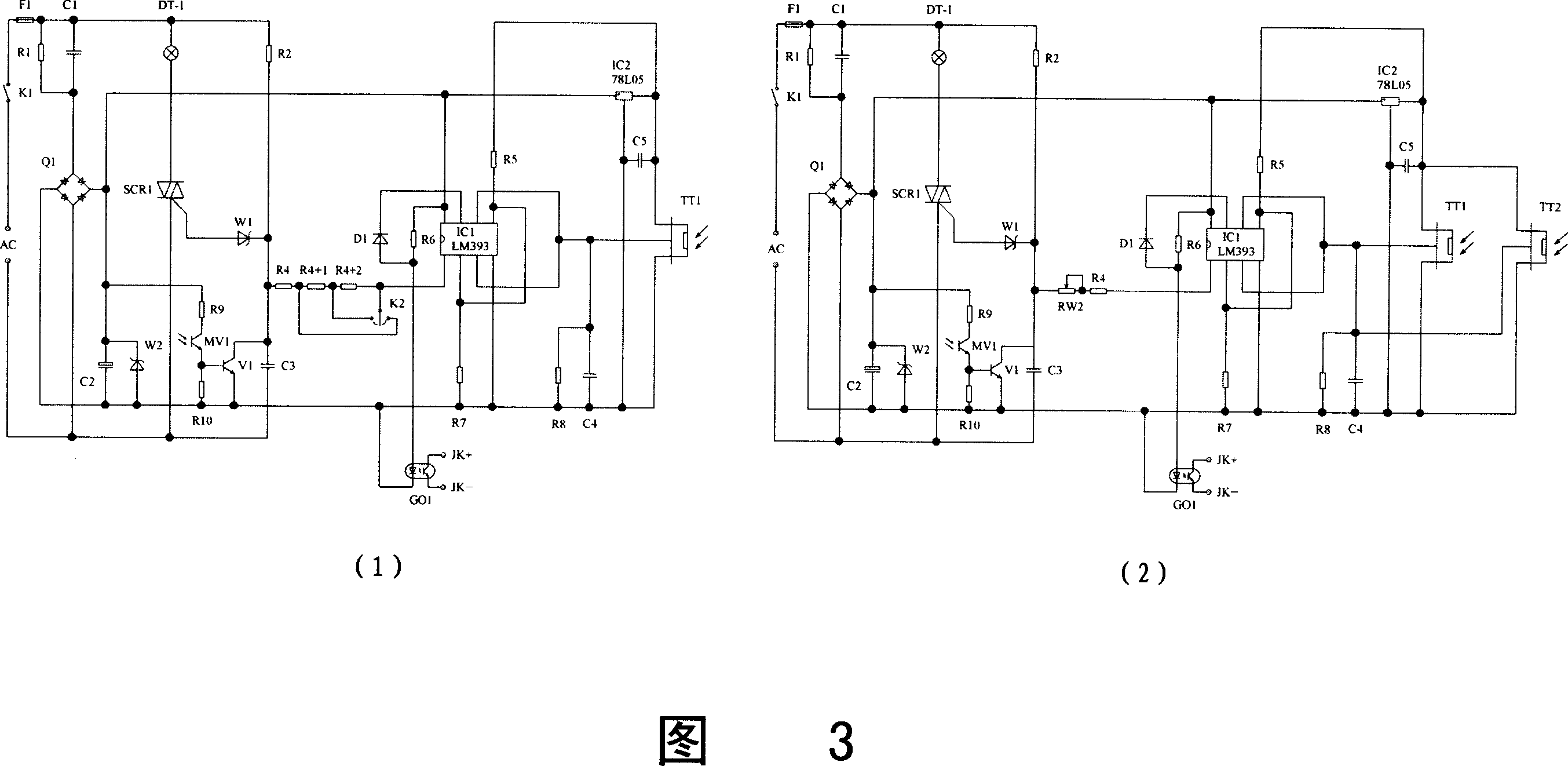
[0052] See (1) in Figure 3. As shown in the figure, it is a schematic diagram of an AC-AC dimming power supply with a bidirectional thyristor (SCR1) as the switching element, only one segmental dimming switch (K2), and a photosensitive probe (MV1).
[0053] In this embodiment, a photosensitive probe consisting of a photosensitive triode (MV1), a flow expansion triode (V1), and resistors (R9) and (R10) is installed on the basis of the previous figure; during the day, the photosensitive triode (MV1) is excited, and the current expansion transistor (V1) is turned on, so that the trigger voltage cannot be established on the delay capacitor (C3), and the bidirectional thyristor (SCR1) does not work; at night, the photosensitive transistor (MV1) As of now, the automatic dimming energy-saving lamps work normally.
[0054] After the photosensitive probe is added, it is not always necessary to turn on and off the dimming power supply through the power switch, and even cancel the power...
PUM
 Abstract
Description
Claims
Application Information
 - R&D
- Intellectual Property
- Life Sciences
- Materials
- Tech Scout
- Unparalleled Data Quality
- Higher Quality Content
- 60% Fewer Hallucinations
Browse by: Latest US Patents, China's latest patents, Technical Efficacy Thesaurus, Application Domain, Technology Topic, Popular Technical Reports.
© 2025 PatSnap. All rights reserved.Legal|Privacy policy|Modern Slavery Act Transparency Statement|Sitemap|About US| Contact US: help@patsnap.com