Compactly designed membrane-type coupling

A coupling and membrane technology, which is applied in the field of membrane couplings, can solve the problems of large space of membrane couplings and achieve the effect of reducing the installation length

Active Publication Date: 2007-04-11
HACKFORTH GMBH
View PDF1 Cites 0 Cited by
  • Summary
  • Abstract
  • Description
  • Claims
  • Application Information

AI Technical Summary

Problems solved by technology

[0004] The drawback of the known membrane couplings is the relatively large space

Method used


Image

  • Compactly designed membrane-type coupling
  • Compactly designed membrane-type coupling
  • Compactly designed membrane-type coupling

Examples


Embodiment Construction

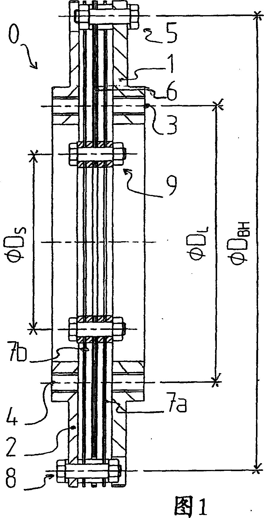
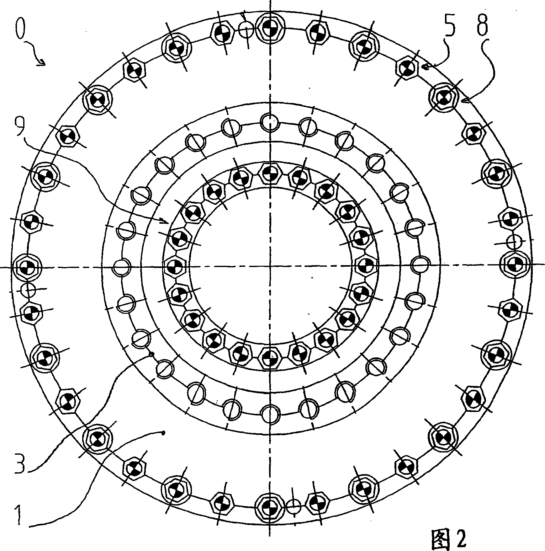
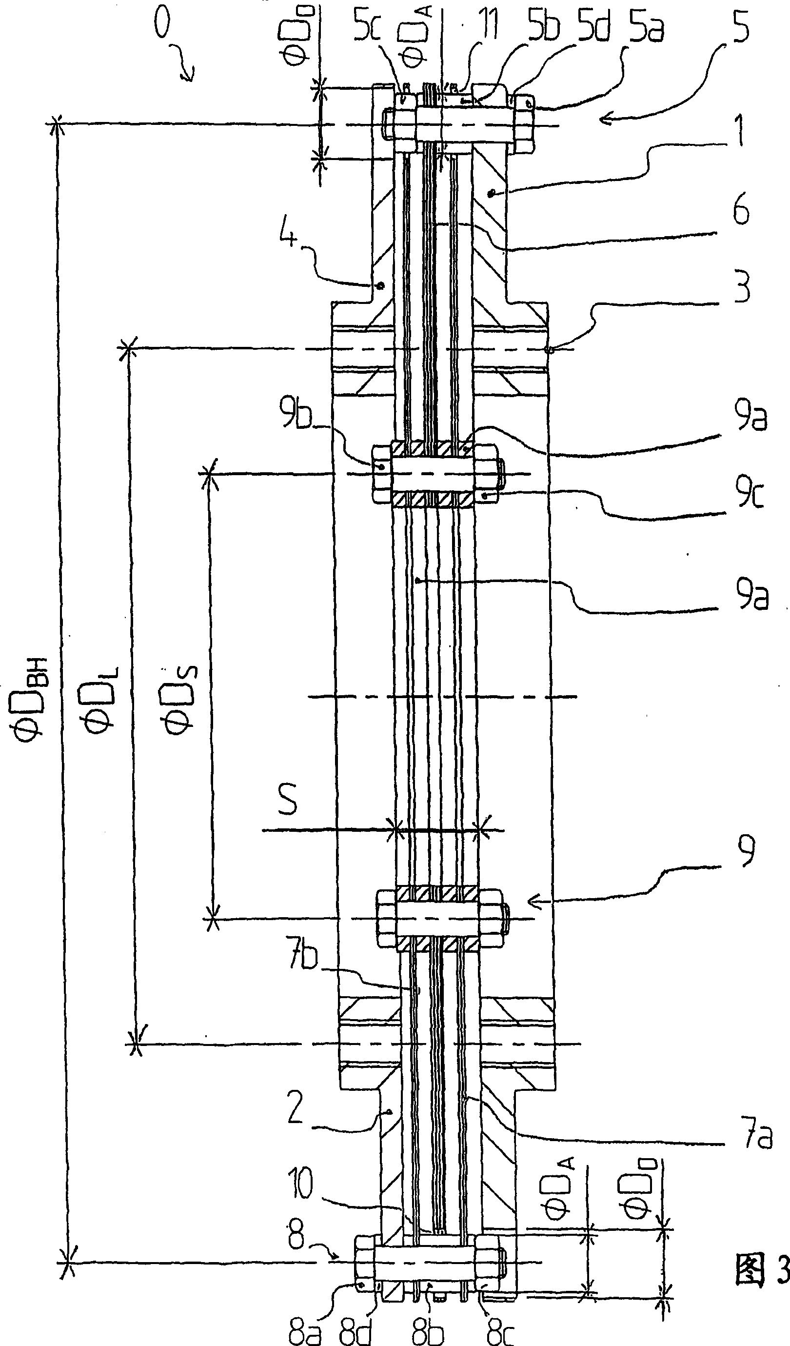
[0017] The membrane coupling is denoted as a whole by the reference numeral 0 . The membrane coupling consists of an input flange 1 and an output flange 2. The flanges 1 , 2 are each equipped with an input perforated disc 3 or an output perforated disc 4 , by means of which the membrane coupling 0 can be connected to machine elements arranged before or after the drive rod. The two perforated discs 3, 4 are concentric with the flanges aligned. In this embodiment the two porous disks 3, 4 have the same diameter D L . For specific application purposes, it can be considered to design the porous discs 3, 4 with different diameters D L . The first type of bolt / sleeve configuration 5 is set at a larger diameter D BH superior.

[0018] A bolt / sleeve arrangement 5 of the first type comprises a bolt 5a, two bushes 5b, a nut 5c and a washer 5d. The input diaphragm pack 6 is fastened to the input flange 1 by means of a first type of screw / sleeve arrangement 5 . The input diaphragm...


PUM


Abstract

The invention relates to a membrane-type coupling (0) comprising an input flange (1) and an output flange (2) which are interconnected via membrane packs (6, 7a, 7b) in order to transmit torque in such a way that an input membrane pack (6) is braced to the input flange (1), two output membrane packs (7a, 7b) that are connected in parallel are braced to the output flange (2), and the membrane packs (6, 7a, 7b) are braced to one another with the aid of a clamping set (9) composed of clamping rings (9a). In order to reduce the volume and weight of such a membrane-type coupling, the input membrane pack (6) is disposed between the two output membrane packs (7a, 7b).

Description

technical field [0001] The invention relates to a membrane coupling, comprising an input flange and an output flange, which are connected to each other through a diaphragm set for torque transmission, that is, the input diaphragm set is fixed on the input flange, and two parallel The provided output diaphragm packs are fastened to the output flange, the diaphragm packs being fastened to each other by a clamping device formed as a clamping ring. Background technique [0002] US 4 492 583 A discloses a coupling consisting of two membrane couplings of the same type connected by a hollow shaft. [0003] The purpose of this type of membrane coupling is in-phase torque transmission between heavily misaligned machine elements. [0004] The disadvantage of the known membrane couplings is the relatively large space. The reason for this is that the diaphragm sets connected in series, ie the input diaphragm set and the two sets of output diaphragm sets connected in parallel, are moun...

Claims


Application Information

Patent Timeline
Patent Type & Authority Applications(China)
IPC IPC(8): F16D3/79
CPCF16D3/79F16D3/72F16D3/50F16D13/64
Inventor H·于克特
Owner HACKFORTH GMBH
Why Eureka
Try Eureka