Laminated flowing cooling water side-jetting sweeping system after high-strength low-alloy steel being rolled

A low-alloy steel, laminar cooling device technology, used in cooling bed, metal rolling, metal rolling and other directions, can solve the problems of poor steel plate, difficult to clean the shape of the plate, and achieve good shape, The effect of excellent plate shape and increased cooling water volume

Inactive Publication Date: 2007-04-18
NANJING IRON & STEEL CO LTD +1
View PDF0 Cites 15 Cited by
  • Summary
  • Abstract
  • Description
  • Claims
  • Application Information

AI Technical Summary

Problems solved by technology

[0003] The purpose of the present invention is to solve the problem that the laminar flow cooling water after rolling is difficult to be purged in the production process of high-strength low-alloy steel such as high-standard pipeline steel, which leads to the problem that

Method used


Image

  • Laminated flowing cooling water side-jetting sweeping system after high-strength low-alloy steel being rolled
  • Laminated flowing cooling water side-jetting sweeping system after high-strength low-alloy steel being rolled
  • Laminated flowing cooling water side-jetting sweeping system after high-strength low-alloy steel being rolled

Examples


Embodiment 1

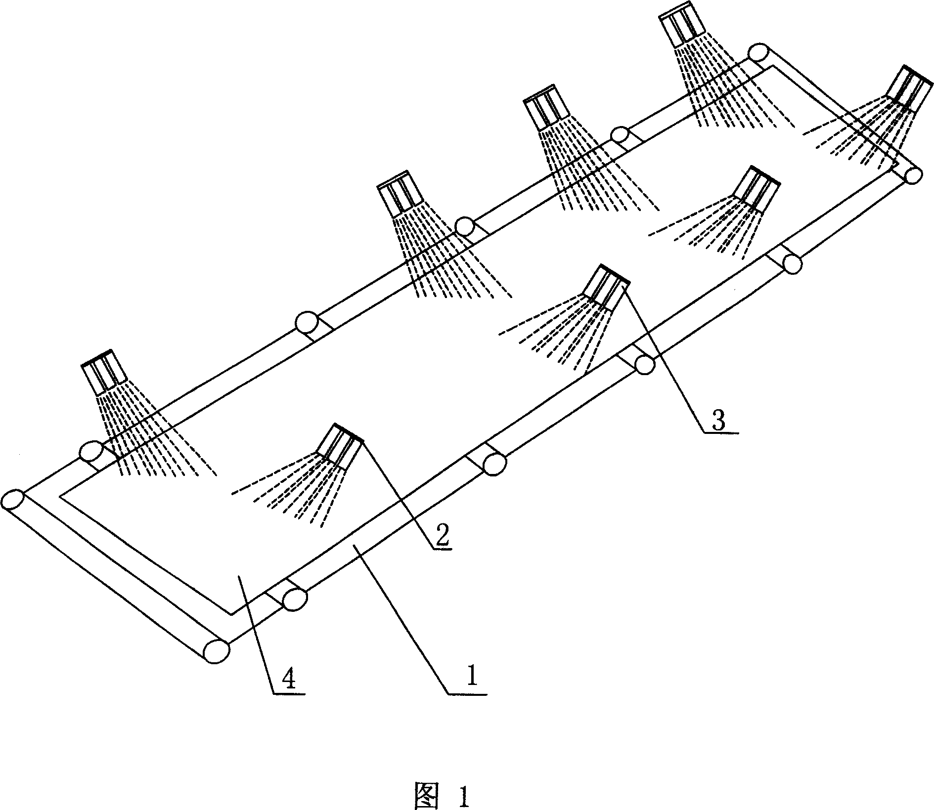
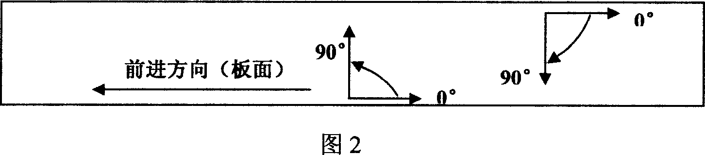
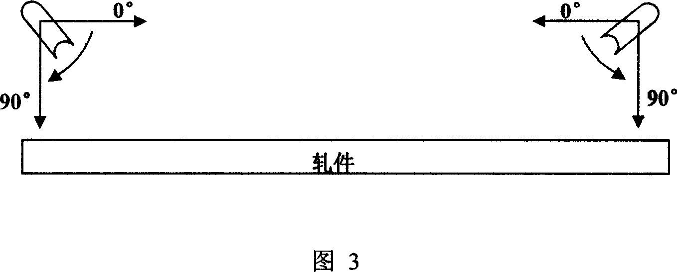
[0022] The structure of this embodiment is shown in FIG. 4 . This embodiment is provided with four groups of side spray devices 2 , and each group of side spray devices 2 is provided with three nozzles 3 . The water pressure of the side spray device 2 is selected between 10-50MPa, and the diameter of the nozzle 3 is selected between 20-100mm. The angle between the axis of the nozzle 3 and the rolling direction is 45°, and the angle between the axis of the nozzle 3 and the horizontal plane of the conveying roller table 1 is 45°. The side spray device 2 is provided with a group on both sides of the conveying roller table 1 before the steel plate 4 enters the laminar flow cooling device, so that the cooling water can be blocked in the laminar flow cooling area to prevent the loss of cooling water, so that the laminar flow cooling can reach Great cooling effect. The side spray device 2 is provided with a group between the strong cooling section and the intermediate cooling sectio...

Embodiment 2

[0024] The structure of this embodiment is shown in FIG. 5 . This embodiment is provided with four groups of side spray devices 2 , and each group of side spray devices 2 is provided with four nozzles 3 . The water pressure of side spray device 2 is 40MPa, and the diameter of nozzle 3 is 80 millimeters. The angle between the axis of the nozzle 3 and the rolling direction is 60°, and the angle between the axis of the nozzle 3 and the horizontal plane of the conveying roller table 1 is 60°. The side spray device 2 is provided with two groups on both sides of the conveying roller table 1 before the steel plate 4 enters the laminar flow cooling device, so that the cooling water can be blocked in the laminar flow cooling area to prevent the loss of cooling water, so that the laminar flow cooling achieve a good cooling effect. The side spray device 2 is provided with a group between the strong cooling section and the intermediate cooling section of the laminar flow cooling device, ...


PUM


Abstract

A side-spray scavenge system for the laminar-flow cooling water on the rolled high-strength low-alloy steel is composed of a conveying roller way for conveying the rolled steel on it, and a laminar-flow cooling unit with at least a group of side sprayers arranged at both sides of said roller way, connected to water inlet tube, and with at least one nozzle.

Description

technical field [0001] The invention relates to a metallurgical cooling system, in particular to a side jet purge system of laminar flow cooling water after high-strength low-alloy steel rolling. Background technique [0002] The 21st century is the second peak period for the construction of long-distance oil and gas pipelines in my country. High-grade pipeline steel is widely used in the long-distance transmission of oil and natural gas. Domestic enterprises with strength and competitiveness have already developed and produced High value-added pipeline steel plates are included in the plan. The reason why pipeline steel is constantly developing towards high steel grade is mainly due to economic benefits and continuous development of metallurgical industry. In the investment of oil and gas pipeline projects, the cost of steel pipes accounts for about 40%. The use of high-grade pipeline steel pipes can reduce the wall thickness, and high-pressure transmission can reduce the p...

Claims


Application Information

Patent Timeline
IPC IPC(8): B21B45/02B21B43/04
Inventor 王道远康永林杨兆根于浩尹雨群李翔余伟牛涛
Owner NANJING IRON & STEEL CO LTD
Why Eureka
Try Eureka