Method and circuit of obtaining wave shape trigger signal of oscilloscope

A waveform triggering and triggering level technology, applied in cathode ray oscilloscope, digital variable/waveform display, instruments, etc., can solve the problems of complex signal process, multi-device requirements, and high requirements, and achieve simple and simplified selection and control process. Circuit structure, precise effect of trigger signal

Inactive Publication Date: 2007-04-18
史松涛
View PDF0 Cites 15 Cited by
  • Summary
  • Abstract
  • Description
  • Claims
  • Application Information

AI Technical Summary

Problems solved by technology

[0004] It can be seen from the above description that because mechanical switches or electronic switches are used to select the trigger source and trigger source coupling mode, and the signal switch must meet the bandwidth and amplitude requirements of the signal, so many devices are used and the device requirements are high; because The comparator generates a waveform trigger signal by comparing two analog signals. The circuit device that processes the trigger source signal has been working in an analog state, so the requirements for the device are high, and it is difficult to ensure the consistency of device performance. It leads to poor circuit consistency; and due to the complexity of the signal process, mutual interference between signal sources is easy to occur

Method used


Image

  • Method and circuit of obtaining wave shape trigger signal of oscilloscope
  • Method and circuit of obtaining wave shape trigger signal of oscilloscope
  • Method and circuit of obtaining wave shape trigger signal of oscilloscope

Examples


Embodiment Construction

[0029] Below according to accompanying drawing and embodiment the present invention will be described in further detail:
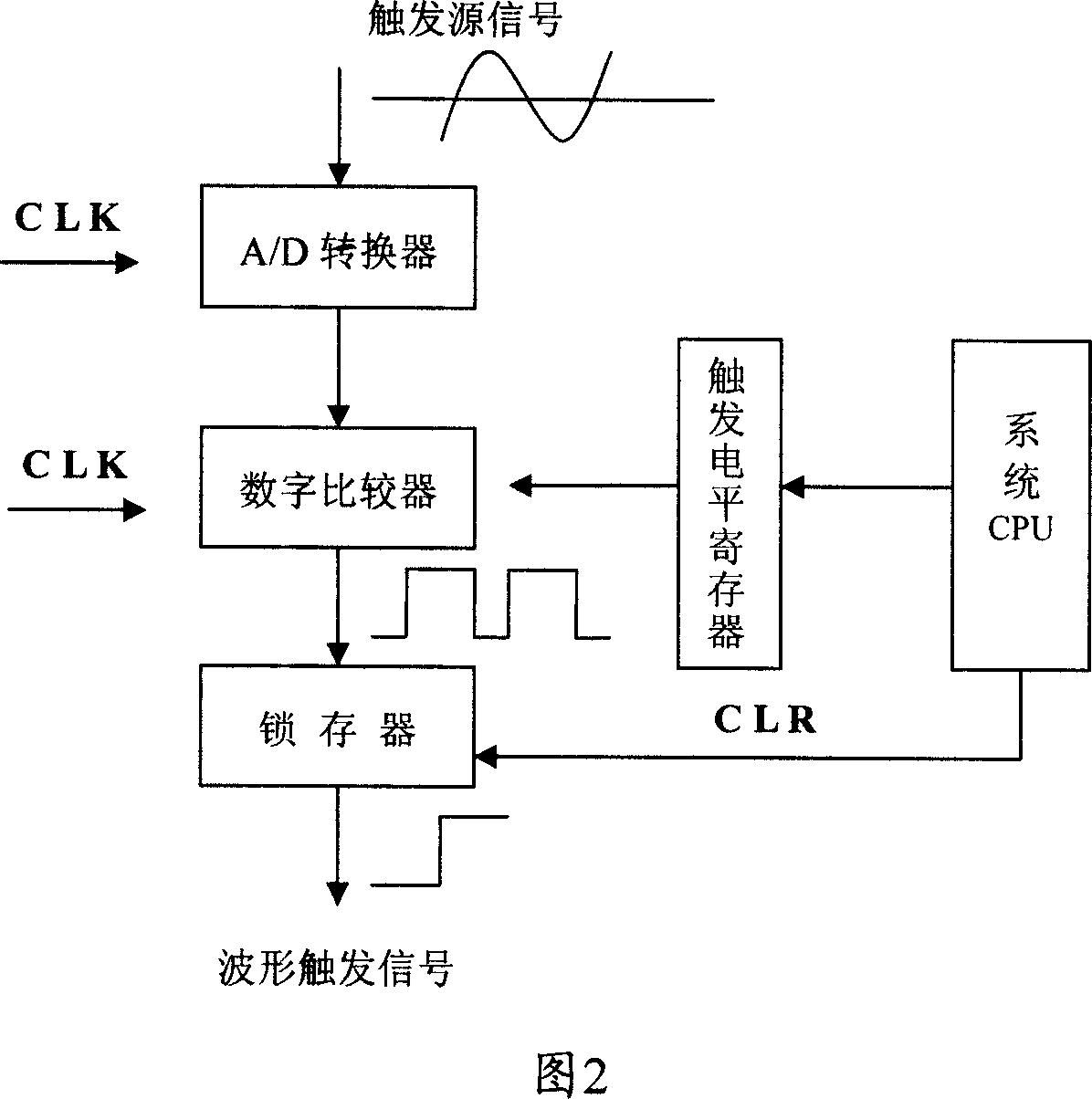
[0030] The main idea of ​​the present invention is to process signals in a digital manner, convert the trigger source signal and trigger level of the oscilloscope into digital signals, and compare them with a digital comparator to generate real-time digital trigger signals.

[0031] The circuit for obtaining the waveform trigger signal is shown in Figure 2. In the figure, the CPU and A / D converter are inherent circuits of the digital oscilloscope system. The A / D converter is used to sample the trigger source signal in real time to obtain the waveform digital signal. There can be multiple source signals, such as the measured signal of channel A or channel B as the trigger source signal, or an external signal as the trigger source signal, and the A / D converter only samples one of the trigger source signals in real time. In addition, the circuit for obtaining...


PUM


Abstract

The invention discloses oscilloscope obtaining waveform trigger signal method and circuit. The method includes the following steps: real time sampling for the trigger source signal to gain waveform digital signal; setting trigger level and storing it in trigger level register; using digital comparator to compare waveform digital signal with trigger level to gain compared impulse; using latch to store rising edge or falling edge of the compared impulse to gain waveform trigger signal. It has the advantages of simple circuit, precise and reliable gained waveform trigger signal, low circuit cost etc.

Description

technical field [0001] The invention relates to oscilloscope technology, in particular to a method for acquiring a waveform trigger signal in the oscilloscope and a circuit for generating the waveform trigger signal. Background technique [0002] Oscilloscopes are widely used in various technical fields, and gradually develop from the original analog circuit to digital circuit, and the digital circuit is small in size and easy to carry, and its excellent circuit performance has won people's favor more and more. Regardless of whether it is an analog oscilloscope or a digital oscilloscope circuit, obtaining a waveform trigger signal is a necessary means and process for the oscilloscope to display the measured waveform synchronously and stably. [0003] An oscilloscope in the prior art uses the method and circuit shown in FIG. 1 to obtain a waveform trigger signal. First, use a mechanical switch or an electronic switch to switch and select the trigger source, that is, select t...

Claims


Application Information

Patent Timeline
Patent Type & Authority Applications(China)
IPC IPC(8): G01R13/00G01R13/32G01R13/22G01R13/20G01R13/02
Inventor 史松涛
Owner 史松涛
Why Eureka
Try Eureka