Photoetching machine table, developing apparatus and developing process thereof

A development device and a development method technology, applied in the field of photolithography, capable of solving problems such as inconsistencies in critical dimensions

Inactive Publication Date: 2007-04-18
AU OPTRONICS CORP
View PDF0 Cites 5 Cited by
  • Summary
  • Abstract
  • Description
  • Claims
  • Application Information

AI Technical Summary

Problems solved by technology

Since more than one photolithography process is usually required to manufacture a circuit structure on the substrate ...

Method used


Image

  • Photoetching machine table, developing apparatus and developing process thereof
  • Photoetching machine table, developing apparatus and developing process thereof
  • Photoetching machine table, developing apparatus and developing process thereof

Examples


Embodiment Construction

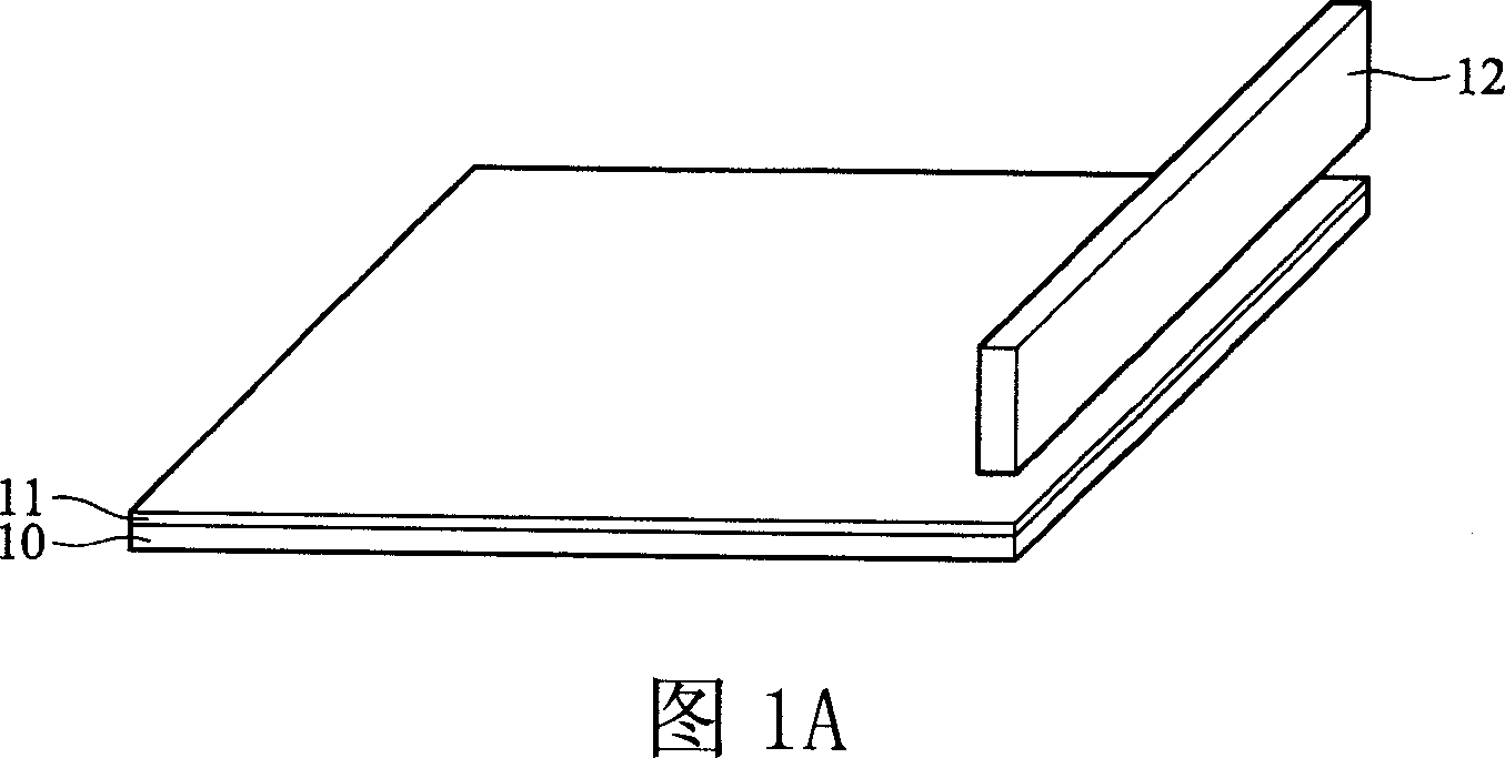
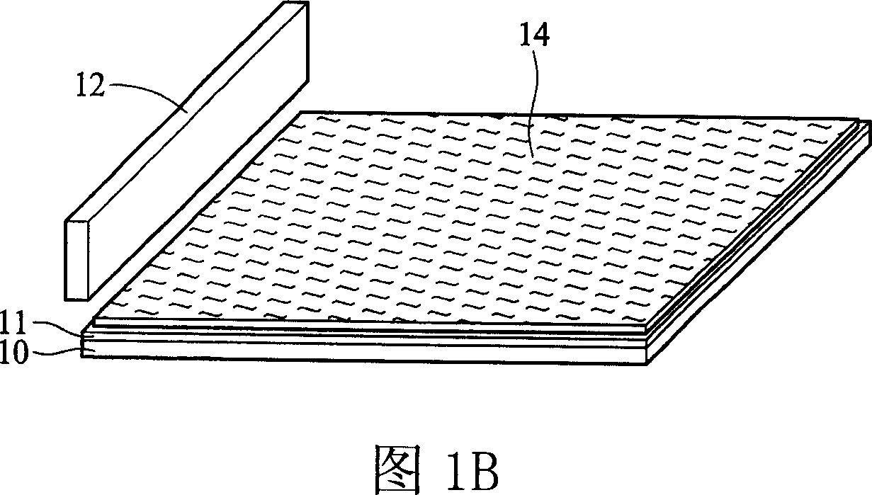
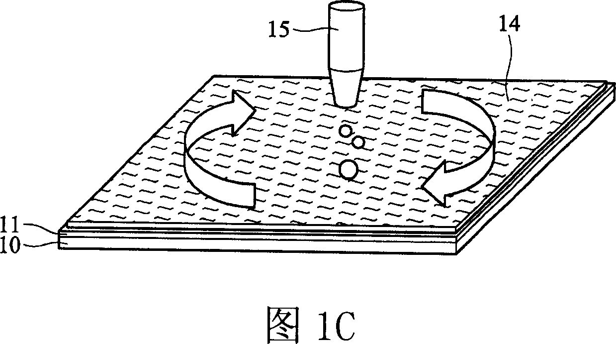
[0024] In the embodiment of the present invention, as shown in FIG. 2A , first, the substrate 20 is fixed by the platform 1 . There is an exposed photoresist 21 above the substrate 20 , and a recovery tank 3 can be provided below to recover the unexposed photoresist or the organic solvent used in the developing process. Above the exposed photoresist 21 is the fluid injector 20 of the present invention.

[0025] FIG. 2B is a top view of FIG. 2A. The material of the substrate 20 includes light-transmitting materials (such as: glass, quartz or similar materials), opaque materials (such as: silicon, ceramics or similar materials), or flexible materials (such as: plastics, rubber, polyester class, polyolefin, polyacyl or similar materials or a mixture of the above), the embodiments of the present invention take a glass substrate as an example. In addition, the structure on the surface of the substrate 20 may be any layer of a circuit structure or a filter structure. On the surfa...


PUM


Abstract

The invention supplies developing unit and method. The unit includes one platform, one base plate has exposed photoresist layer, and one fluid injector injected the developer to the base plate at the first time to develop the exposed photoresist and injected one fluid to the base plate at the second time to clean it. Thus it can process pre-cleaning and pre-developing for the photoresist to avoid the under developing. The critical dimension of the processed whole base plate tends to consistent. This can greatly improve developing technology yield.

Description

technical field [0001] This invention relates to photolithographic processes, and more particularly to apparatus used in the developing step. Background technique [0002] Photolithography is the most important process in the manufacture of electronic components. How to copy the layout that can be recognized by human eyes to components with micron-nanometer circuits depends on the quality of the photolithography process. The photolithography process generally includes the following steps: substrate cleaning, coating photoresist, soft bake), exposure, development, and subsequent processes such as hard bake, ion implantation, ion treatment or etching, removal Photoresist. In order to obtain a better photolithographic effect, the photoresist manufacturing method is improved according to the existing technology, the exposure process of the stepper is improved, and a different exposure light source is even selected. [0003] Most of the improvements still focus on the photores...

Claims


Application Information

Patent Timeline
IPC IPC(8): G03F7/30G03F7/20H01L21/027
Inventor 王明山曾振助郑雅夫林明辉
Owner AU OPTRONICS CORP
Why Eureka
Try Eureka