High-speed CCD camera data synthesizing system

A data synthesis and camera technology, which is applied to measuring devices, signal generators with multiple pick-up devices, instruments, etc., can solve problems such as wasting system resources, reduce system volume, reduce pixel output rate, and save system cost effect

Inactive Publication Date: 2007-04-18
INST OF OPTICS & ELECTRONICS - CHINESE ACAD OF SCI
View PDF0 Cites 16 Cited by
  • Summary
  • Abstract
  • Description
  • Claims
  • Application Information

AI Technical Summary

Problems solved by technology

The shooting interval calculated according to the actual flight altitude and speed and the required ground coverage is greater than 4s, while the camera data readout time is only about 233ms, which means that the camera will be in a non-working state for a long time, which seriously wastes system resources

Method used


Image

  • High-speed CCD camera data synthesizing system
  • High-speed CCD camera data synthesizing system

Examples


Embodiment Construction

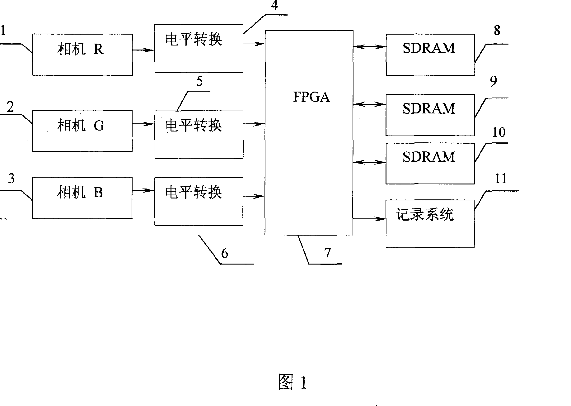
[0008] As shown in Figure 1, the present invention comprises three-way parallel high-speed CCD camera R (1), camera G (2) and camera B (3), three-way interface level conversion chip (4,5,6), FPGA (7 ), a three-way cache unit SDRAM (8, 9, 10) and a recording system (11).

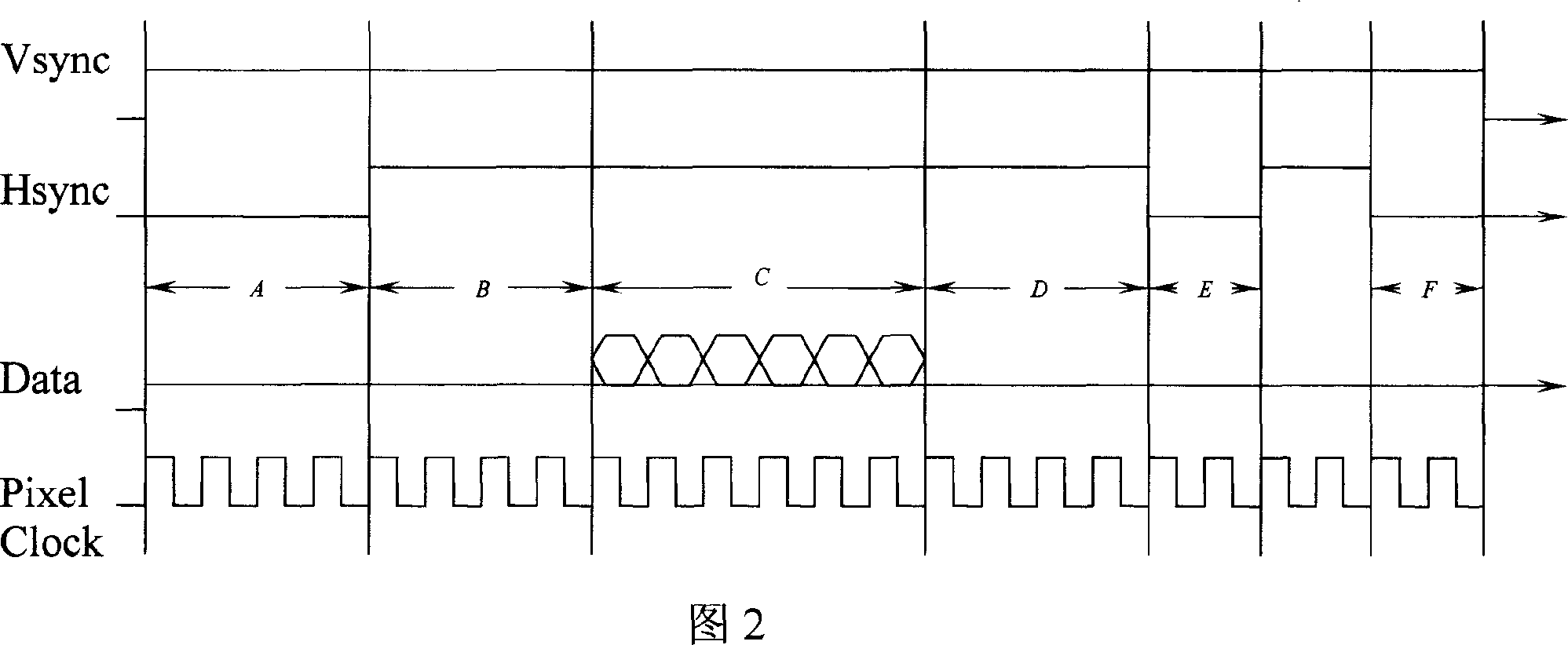
[0009] When the three CCD cameras start to work, the CCD image data is sequentially read in through the external synchronous clock and line and field clock signals. Since the CCD camera data interface is an RS422 signal, it must be converted into a TTL signal by a level conversion chip and written into the FPGA. Considering that the initial states of the three cameras cannot be exactly the same, first write the data of the three cameras into the three FIFOs in the FPGA respectively, and use the read enable logic control of the three FIFOs by the FPGA to realize the synchronous readout of the data of the three FIFOs. Then, the three-camera data synchronized by the FIFO is constructed in the FPGA internal SDRA...


PUM


Abstract

The invention is a high speed CCD camera data synthesizing system, converting three parallel input continuous data streams of high speed CCD cameras through three interface level conversion chips into TTL signals to be written in an FPGA, respectively, and synchronizing the three high speed CCD cameras by FIFO of the FPGA; writing the three synchronized data into three SDRAM chips, respectively, and constructing SDRAM controller in the FPGA to implement dynamic and real-time buffer storage of the three data; synthesizing the three buffer-stored data by the FPGA and converting into LVDS signal by internal level converting circuit of the FPGA to be sent to the next processing unit-recording system. And it extremely raises system efficiency and has universality, applied to CCD cameras of different resolutions.

Description

technical field [0001] The invention relates to a high-speed CCD camera data synthesis system, which belongs to the field of high-speed real-time data processing. Background technique [0002] In the field of aerial photogrammetry, in order to obtain high-definition color digital images, multiple cameras (usually three cameras: camera R, camera G, and camera B) are often used to obtain image information and fuse the image information. Since the amount of image information is too large to be processed in real time, all images need to be recorded on a high-speed hard disk in real time during the flight. The original design was to record the image data of three 2K×2K cameras with three recording systems, and the system was very large. The shooting interval calculated based on the actual flight altitude and speed and the required ground coverage is greater than 4s, while the camera data readout time is only about 233ms, which means that the camera will be in a non-working state...

Claims


Application Information

Patent Timeline
Patent Type & Authority Applications(China)
IPC IPC(8): H04N9/09G01C11/00
Inventor 陈苏婷杨世洪吴钦章姚俊
Owner INST OF OPTICS & ELECTRONICS - CHINESE ACAD OF SCI
Why Eureka
Try Eureka