
Sand-drainage construction system for diversion channel

A technology of diversion canal and structure, applied in the field of sand discharge system, can solve problems such as affecting the service life of hydraulic turbines and difficult to remove sand and gravel.

Active Publication Date: 2007-04-25
四川希望深蓝能源化工有限公司
View PDF0 Cites 9 Cited by
  • Summary
  • Abstract
  • Description
  • Claims
  • Application Information

AI Technical Summary

Problems solved by technology

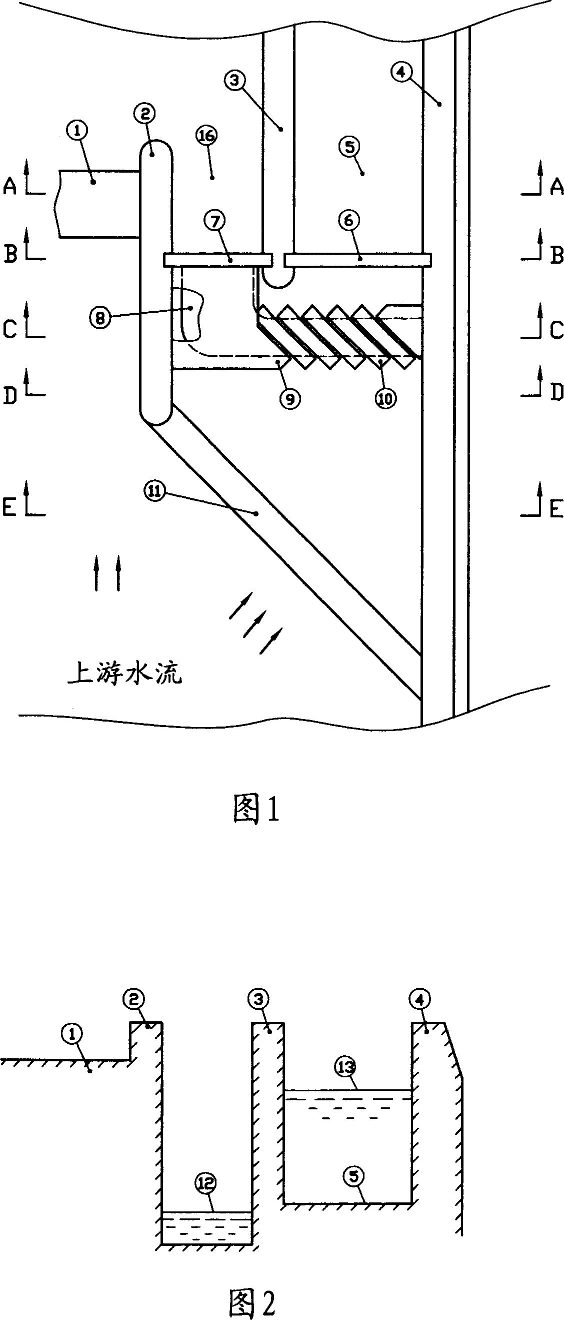
[0003] In order to overcome the disadvantages that the sand and gravel deposited at the entrance of the diversion canal are not easy to be removed and affect the service life of the water turbine, the present invention sets a grit chamber in the gravel deposition area on the upstream side of the water diversion gate and the sand washing gate

Method used


Image

  • Sand-drainage construction system for diversion channel
  • Sand-drainage construction system for diversion channel

Examples


Embodiment Construction

[0013] As shown in Figure 1, the system consists of the main channel dam 1, diversion dike 2, diversion dike 3, right dike 4, diversion channel 5, diversion sluice 6, sand washing channel 16, sand sluice gate 7, main channel The sand blocking weir 11, the grit chamber 8, the sand washing cover 9 and the sand introduction cover 10 are composed. The right side of the main channel dam 1 is connected with the dike 2, and the left side of the main channel dam 1 is connected with the left side embankment. The left side channel is omitted and not shown in the figure. Between the upstream end of the diversion embankment 2 and the right embankment 4, there is an inclined very long main channel sand retaining weir 11, and between the middle section of the diversion embankment 2 and the right embankment 4, a diversion embankment 3 is constructed in parallel. There is a sand washing gate 7 between the upstream end of the diversion dike 3 and the diversion dike 2 , and the sand washing cha...


PUM


Abstract

The invention discloses a structural system for excluding sand in diversion canal of hydraulic station, comprising waste water storage dam of draining line, diversion bank, guide bank, right bank, conduit, diversion gate, sand flushing channel, sand flushing gate, waste sand storage weir of draining line, sand slot, cover of sand flushing and cover of sand guiding. Riverway is divided into draining line, sand flushing channel and conduit by diversion and guide banks. There is L-shape sand slot on the one side of the upper of sand guiding and flushing channels, of which one end is started from right bank and parallel to the direction of diversion gate, and the bottom is inclined to deepen from starting end of right bank to left end. Cover of sand guiding is fixed on the sand slot parallel with diversion gate in certain distance. The left end of sand slot ends to the position of diversion bank and gate of sand flushing and is shaped L, of which the bottom is inclined to deepen to gate of sand flushing. Cover of sand flushing is set on the sand slot to gate of sand flushing. The system can exclude sand thoroughly and automatically.

Description

Technical field [0001] The invention belongs to a sand discharge system of a hydropower station, in particular to a sand discharge structure at the entrance of an aqueduct. Background technique [0002] Generally, there is a gravel deposition area at the entrance of the diversion channel of a high-head hydropower station. When the gravel entrained by the upstream water flow reaches a certain amount, the sand washing gate next to the diversion channel is opened, and the water flowing through the sand washing gate will dispose of the gravel in the nearby deposits. Take advantage of the trend and rush downstream. However, this sand flushing method is ineffective. The sand and gravel in the deposition place a little far away from the sand washing sluice is not easily washed away due to the lack of momentum of the water flow, and there are still a lot of sand and gravel deposited near the diversion channel. These gravels are easy to enter the diversion channel and reach the wate...

Claims


Application Information

Patent Timeline
IPC IPC(8): E02B8/02E02B9/02
CPCY02E10/22Y02E10/20
Inventor 刘永言
Owner 四川希望深蓝能源化工有限公司
Learn More